My new circuits!!!

   / My new circuits!!! #1  

jgrreed

Platinum Member
Joined
Jun 3, 2008
Messages
787
Location
Regina, Saskatchewan
Tractor
JD 4720
OK guys, I stopped by the shop today to see what's gone on so far on adding my new circuits. There was a small kerfuffle re: the cost of the install, so I was too flustered to snap pics of the tractor, but I'll get those to you soon.

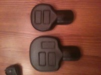
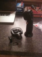
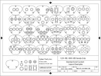
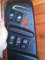
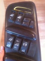
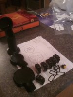
In the pic below are the bits of that I received from Otto for my controls and grips. A big thanks to Peter at Interior Electronics in Kelowna for his help in getting the parts, and to Steve Redlich at Otto for his coaching in what I need.

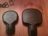
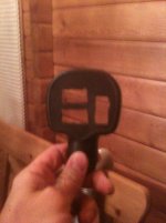
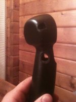
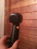
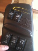
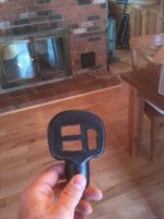
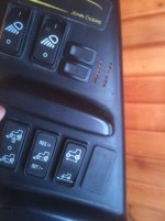
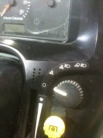
On the left are the grips with the faceplates detached (the second grip is at the shop for sizing). The sketch is how I'm going to cut in the holes for the rocker switches. The lone rocker on the lower left is the ON/OFF/ON switch that I'm going to use for the continuous ON circuit if I ever build a hydraulically powered weed wacker. It will go on the dash near the between the steering wheel and the throttle. The yellow pushbutton is for my horn project, which I'll deal with when the summer comes. The row of 5 rockers are the momentaries that are going to run the circuits. Below them are the gaskets to seal up the switches.

I'm about to start drawing and cutting..... wish me luck!!! Pics to follow.

-Jer.
 

Attachments

  • Jer's new toys, assembly required.jpg
    Jer's new toys, assembly required.jpg
    245.9 KB · Views: 340
   / My new circuits!!! #2  
It's about friggin time we see some progress:laughing::laughing: Gonna use a 10 blade to cut them holes?

Talk to you soon;)
 
   / My new circuits!!! #3  
Interesting. Can you link this thread into another that might give some background info?
Must be more to the story. :)
 
   / My new circuits!!!
  • Thread Starter
#4  
Ken - I wish like h**l i could have!! - the Dremel isn't the most precise tool in the league without your subject being very still, clamped down, and under a GA, but that's nothing a little silicone won't cover up!!

Beenthere - Oh there's lot's more to the story....

You can read here:

http://www.tractorbynet.com/forums/hydraulics/134859-proportional-electrohydraulic-systems.html

.... or you can take this synopsis. I wanted to add some more hydraulic circuits to my tractor about 2 years ago. I started sniffing around and decided that I wanted to do a custom, very fancy, very involved proportional system. I then dropped off the TBN map for about a year to focus on some 'life stuff'. By this time I had come to my senses in more ways than one.....

When I moved to SK I actually needed at least one new circuit for a snow blade, so I decided to go ahead. I was able to refresh and draw on a lot of the research I did and advice I was given 2 years ago, and here I am now.

I still opted to go with an electrohydraulic system, but not proportional.

Here is what i've been left with at the end of the evening with my Dremel, some black silicone, and about 300$ worth of parts from Otto......

The smaller grip is for the loader joystick and the bottom rocker will control the grapple or snowblade. The top rocker is actually a dud for the time being, it's just there for possible future (ie if I get around to building my PTO driven high-flow hydraulic driven snowblower to hang from my loader). The yellow push button is what I use when I'm too close for missiles..... or if I need to blow the yet-to-be-installed horn.

The larger grip is going to go on the 3pt control lever. The bottom horizontal rocker will be for angling a blade, or rotating the chute on my blower. The top one will be for the tilt of top 'n tilt, and the vertical one is for the top of the top 'n tilt.

Yes, before someone notices, the top horizontal switch is a little cock-eyed.....

The last remaining switch is the one for the dash for the ON/OFF/ON wiring.

There's a ways to go yet, but most everything else will be done at the hydro shop. Hopefully be done by early next week.....

-Jer.
 

Attachments

  • IMG_0379.jpg
    IMG_0379.jpg
    294.8 KB · Views: 174
  • IMG_0380.jpg
    IMG_0380.jpg
    308 KB · Views: 155
  • IMG_0385.jpg
    IMG_0385.jpg
    264.1 KB · Views: 173
  • IMG_0381.jpg
    IMG_0381.jpg
    265.4 KB · Views: 161
  • IMG_0387.jpg
    IMG_0387.jpg
    247.9 KB · Views: 182
  • IMG_0382.jpg
    IMG_0382.jpg
    259.2 KB · Views: 157
   / My new circuits!!! #5  
There are plenty of the electronic joysticks on the Internet, but if you just want to make your own, no reason why not.


8901-RB Handy-Grip
 

Attachments

  • LT1.jpg
    LT1.jpg
    6.3 KB · Views: 137
  • lt2.jpg
    lt2.jpg
    6.6 KB · Views: 134
  • lt3.jpg
    lt3.jpg
    204.1 KB · Views: 159
   / My new circuits!!!
  • Thread Starter
#6  
There are plenty of the electronic joysticks on the Internet, but if you just want to make your own, no reason why not.


8901-RB Handy-Grip

I couldn't find anything that suited my likes (and a few needs).... and at the end of the day, it was very, very fun!!!

-Jer.
 
   / My new circuits!!! #7  
The reason that I suggested those are, that they are probably water proof, and stand up to the elements better.
 
   / My new circuits!!!
  • Thread Starter
#8  
The reason that I suggested those are, that they are probably water proof, and stand up to the elements better.

Mine are waterproof and dust proof, not mil-spec, but IP68S (whatever that means). They'll stand up to the elements fine. My cuts weren't exactly ultraprecise, but I sealed them with the gaskets provided, and silicone.

-Jer.
 
   / My new circuits!!! #9  
The IP68 code means that they are waterproof to 50 ft. Good deal.
 
   / My new circuits!!!
  • Thread Starter
#10  
The IP68 code means that they are waterproof to 50 ft. Good deal.

Perfect, 'cause I added a 51' snorkel as well..... ;)

I'm starting a lakefront-weed clearing business.....

-Jer.
 
 
Top