You are using an out of date browser. It may not display this or other websites correctly.
You should upgrade or use an alternative browser.
You should upgrade or use an alternative browser.
Old Hydraulic Gear Pump
- Thread starter NJ Toolnut
- Start date
- Views: 8939

/ Old Hydraulic Gear Pump
#11
OP
NJ Toolnut
New member
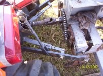
I had a feeling that pump would work just by the way you 2 were talking. Here is the way I did mine and the cycle time is good, I run my tractor from 1500 t0 1800 rpm. Just make sure you get the side load right.
Thanks Leejohn, that's an interesting design. Do you remember what size chain you used? How tight is it? This design will put some radial loading on the pump shaft even with some slack in the chain, have you used it a lot?
Farmerford
Platinum Member
- Joined
- Dec 9, 2006
- Messages
- 733
- Location
- Columbus, Georgia
- Tractor
- Kuborta B2400, L2900, L4330; Caterpillar D3B, John Deere 455D
Stan:
Looks like you have about worked it out.
Regarding radial loads, in the gear pump the roughly half of each gear toward the outlet is under high pressure from the fluid being pumped. The other half of each gear toward the inlet side is under very low pressure; a low vacuum in most cases. If you draw a line between the centers of the two shafts, the parts of the gears on the outlet side of the line are under pressure from the fluid and the the parts on the inlet side are under very little, if any pressure. Of course, the pressure change around the gear from maximum near the outlet to zero near the inlet is on a gradient, but it is convenient to think of pressure on the outlet side and none on the inlet side.
The pressure on the outlet side tends to push the shafts apart and toward the inlet side. Therefore, the bearing load on the shafts is on the half of each bearing toward the inlet side, since the pressure is pushing the shafts back toward the inlet side.
It seems to me better to locate the pump so that the radial load of the drive chain does not add to the load on the bearing for the driving shaft nearest the sprocket. That means the drive side of the chain should be pointing away from the half of the bearing toward the inlet, perhaps even a bit angled in toward the outlet. Generally, the drive side of the chain should point toward the power sprocket in the same direction as the outflow of fluid from the pump case (assuming the ports are on the "outside" of the housing and not on the ends).
I admit that the effect of this arrangement is to add some radial load to the fluid pressure load on the other end of the driven shaft due to the moment of the chain force around the sprocket end bearing. But unless the sprocket is way out on the end of the shaft, that unfavorable force on the offside bearing should be less than the favorable force on the sprocket side bearing. Indeed, if the sprocket is placed very close to the sprocket side bearing, the unfavorable additive force on the offside bearing will be only a fraction of the reductive force on the sprocket side bearing.
At least that all made sense to me on the couple of occasions I have chain driven a gear pump that was probably not designed for a chain drive. And so far neither one failed, though I admit they don't get a lot of use. But since you cannot avoid a radial load in some direction, it makes sense to me to select the direction that logically does the most harm.
I am looking forward to pictures.
Leejohn
Elite Member
I used #50 chain and it is tighten just enough to take the slack out of it. Yes I have used it alot. That pump was put on I would guess about 5 years ago, the old pump I didn't have the radial load right and I builded it in the early 80's. That log splitter has split a lot of wood. The spec's you got should of gave you where the radial loading are. If you blow the picture up you can see the chain adjuster.
OP
NJ Toolnut
New member
...If you draw a line between the centers of the two shafts, the parts of the gears on the outlet side are under pressure from the fluid and the the parts on the inlet side are under very little, if any pressure. The pressure on the outlet side tends to push the shafts apart and toward the inlet side. Therefore, the bearing load on the shafts is on the half of each bearing toward the inlet side, since the pressure is pushing the shafts back toward the inlet side. It seems to me better to locate the pump so that the radial load of the drive chain does not add to the load on the bearing for the driving shaft nearest the sprocket. That means the drive side of the chain should be pointing away from the half of the bearing toward the inlet, perhaps even a bit angled in toward the outlet. Generally, the drive side of the chain should point toward the power sprocket in the same direction as the outflow of fluid from the pump case (assuming the ports are on the "outside" of the housing and not on the ends).
I admit that the effect of this arrangement is to add some radial load to the fluid pressure load on the other end of the driven shaft due to the moment of the chain force around the sprocket end bearing. But unless the sprocket is way out on the end of the shaft, that unfavorable force on the offside bearing should be less than the favorable force on the sprocket side bearing. Indeed, if the sprocket is placed very close to the sprocket side bearing, the unfavorable additive force on the offside bearing will be only a fraction of the reductive force on the sprocket side bearing.
At least that all made sense to me on the couple of occasions I have chain driven a gear pump that was probably not designed for a chain drive. And so far neither one failed, though I admit they don't get a lot of use. But since you cannot avoid a radial load in some direction, it makes sense to me to select the direction that logically does the most harm.
Farmerford,
Thanks for your interest, and especially for your analysis.
I fully agree regarding the forces at work on the pump interior, but I believe it may be possible to design a chain drive that eliminates external radial loading on the pump shaft. I think we can safely assume that Commercial Shearing took these interior forces into account when they designed the pump and specified the shaft bearings, but it seems unlikely they considered external radial loading on the pump shaft since pumps installed as intended would not be exposed to such loading.
If I can design a case for the chain drive that uses radial ball bearings to support both ends of the shaft attached to the small sprocket for the pump, and then add a frame bolted to the exterior rear of this case to which the pump is attached in turn, and then ensure that the two bores on each side of the case for the small sprocket shaft outer bearing races as well as the bore in the frame external to the chain drive case for the pump pilot are all concentric, would not such a design eliminate radial loading on the pump shaft? Such a design could use interior splines on the small sprocket shaft to couple to the external splines on pump shaft and transfer torque to the pump, and would feature oil seals in the bores on both sides of the sprocket case exterior to the small sprocket shaft bearings to prevent leaks. The side of the case closest to the tractor could be bolted directly to the back of the tractor using four existing large bolts, and could be bored to index to the pilot diameter of the PTO shaft boss. I think PTO shaft bearings are designed to be capable of withstanding the radial load imposed by the large sprocket and would not require outboard bearing support.
Leejohn,
Thanks for your response.
I agree #50 chain can easily deal with the torque involved, and its good to hear your second design was an unqualified success. I suspect #40 chain would also work, but it would probably wear faster. Another consideration around chain size is availability of sprockets with the correct numbers of teeth to obtain the RPM ratio I currently believe is optimum, as well as interior and exterior diameters that will work for the shaft diameters and case size. I will try to enlarge the image you provided to see the details of your chain tensioner.
I'm still not sure that it would be best to drive the pump at 1900 RPM to enable full advantage to be taken of the available 28.5 PTO HP. I don't want to labor the tractor too much, but I also want reasonable cycle times. Do you know how much flow you obtain from your pump at 1500-1800 RPM?
The cylinder I have (also from the same dump truck) has an external diameter of 4.5" and is 15" long. My woodstove takes rounds up to 19" long. I believe that this will work, but that for some hard to split chunks I may need to insert a block of wood in front of the end plate in order to allow the wedge to travel the full length of the chunk I'm trying to split. Does anyone have any thoughts about this situation?
This cylinder has either 1/2" or 3/4" female NPT connections for the hoses. It obviously worked with this pump on the dump truck, but I'm concerned about restriction. I also need to think about what valve makes the best sense, again considering minimizing restriction. Finally, I'm wondering whether it would make good sense to set relief at less than the rated pressure of 2500 psi in order to minimize wear. I really need to review all the informative design-related posts on this board.
Stan
oldnslo
Super Member
NJ,
Any idea on what pressure the cylinder is rated for? Changing the pressure from 2250 to 2500 would make very little difference in the wear on your pump. You would only see this pressure when splitting hard wood.
If cylinder OD is 4.5" I would guess for operating at 2500- 3000 PSI that it is a 3 1/4" diameter bore. If 4" bore it would only be rated to 1500 PSI.
OP
NJ Toolnut
New member
NJ,
Any idea on what pressure the cylinder is rated for? Changing the pressure from 2250 to 2500 would make very little difference in the wear on your pump. You would only see this pressure when splitting hard wood.
If cylinder OD is 4.5" I would guess for operating at 2500- 3000 PSI that it is a 3 1/4" diameter bore. If 4" bore it would only be rated to 1500 PSI.
oldnslo,
Thanks for your response. It really got my attention and has given me more to consider!
I have no idea what pressure the cylinder is rated for, but it was used with this pump, which is rated for 2500 psi. Cylinder OD is definitely 4.5", but I have not had it apart to measure its bore diameter. I was not aware cylinders exist that are only rated for 1500 psi. How likely would it be that a 1500 psi rated cylinder would be combined with a 2500 psi rated pump? I suppose the dump truck's hydraulic system could have been limited by hydraulic relief to 1500 psi. Now that you've brought it to my attention, it seems more likely to me that the cylinder is rated for the higher pressure, with a bore of 3.25" and wall thickness of 3/4" but this is just a WAG based on possibly flawed logic. Obviously, bore diameter will profoundly affect tonnage the ram can exert--about 10 tons for a 3.25" bore vs. close to 16 for a 4" bore, assuming both are operating at 2500 psi. I previously (and ignorantly) assumed 1/2" cylinder wall thickness without considering/realizing it would need to be thicker to withstand 2500 psi.
I suppose I could measure the cylinder volume by filling it with oil and cycling it into a bucket, assuming I can exert enough force on the ram. I could then subtract this volume from a volume calculated using the cylinder OD and stroke length to determine cylinder wall thickness by difference. Alternatively, I could remove the shaft end cap and measure, but it looks like this would require a really large face spanner wrench. Finally, I could just use it and hope for the best. If it failed, would it be catastropic in nature or would it only involve seal failure? It certainly would not explode like a compressed air tank, but I guess it could rupture. Is it even possible to predict the failure mode? If it turns out the ram can only exert ten tons, is that sufficient force for a splitter?
You said something else that also got my attention, that I would only see this pressure splitting hard wood. I think (based on my limited knowledge of hydraulics) the cylinder itself would only see this pressure if it stalled while splitting hard wood, but the pressure side of the system upstream from the valve that controls flow to the cylinder will always see whatever the relief pressure is set at, correct?
Stan
oldnslo
Super Member
NJ,
Cylinder failure: This would typically not be an explosive failure. What I would expect is either a seam splitting and leaking or possibly the cylinder wall ballooning. Most cylinders have a 3:1 safety factor so the odds of any failure are reduced.
"You said something else that also got my attention, that I would only see this pressure splitting hard wood. I think (based on my limited knowledge of hydraulics) the cylinder itself would only see this pressure if it stalled while splitting hard wood, but the pressure side of the system upstream from the valve that controls flow to the cylinder will always see whatever the relief pressure is set at, correct?"
NJ,
You will only see pressure when the flow is restricted so as long as the valve is held fully shifted the pressure to the cylinder will be very similar to the pressure before the valve. Only difference is line losses.
No, pressure line to the valve should not see system pressure unless there is a restriction to flow or you have a closed center valve. If you partially shift the valve or have to small of lines you will see build pressure in the inlet to the valve.
examples:
17 GPM in 3/4" ID hose is around 14 feet per second (FPS) velocity and will drop around 1 PSI per foot of hose or 10 PSI in ten feet
17 GPM in 5/8" ID hose is around 18 FPS velocity and will drop around 2 PSI per foot of hose or 20 PSI in ten feet
17 GPM in 1/2" ID hose is around 29 FPS velocity and will drop around 5 .75 PSI per foot of hose or 57.5 PSI in ten feet
This does NOT include and hose ends or fittings..
A good system design will always have some pressure on the pump to keep it lubricated. Gear pumps best guess is around 75 - 100 PSI. Piston pumps typically around 300 PSI
OP
NJ Toolnut
New member
Thanks for correcting my thinking, oldnslo!
Here are my take-aways from your response:
Cylinder failure: Low risk of failure, and low probability of harm to the operator (me) if it were to actually occur. Bottom line, go with the cylinder I have and hope for the best. The worst case would result in a ruined cylinder and spilled hydraulic oil.
Hydraulic circuit and system pressure: The only time the system is pressurized is when the open center control valve (the type required for hydraulic circuits that use positive displacement pumps like gear pumps) is actuated, either for forward ram movement or ram retraction. The rest of the time, the system pressure is governed by system frictional losses. This is because until the control valve is actuated, hydraulic oil continuously flows from the pump outlet through the open center and back through the filter to the tank. Pressure relief valves are usually included in open center control valves, but they function only when the system pressure rises after control valve actuation to a level high enough to overcome the force of the spring holding the relief valve closed.
Pressure drop as a function of hose size: Bigger diameter is better to limit restriction and frictional heating. Sharp bends should also be avoided when possible. Some pressure always present due to frictional losses but it is needed to ensure pump lubrication.
Do I now have this all correct?
Stan
oldnslo
Super Member
Stan,
I would suspect that your cylinder is fine. If this is a welded cylinder Vs Tie rod style. Tie rod style has 4 rods with threaded ends that are used to hold the end caps onto the barrel. If welded style a possible way to guesstimate wall thickness is to look in one of the ports unless they welded onto the end caps? If welded onto the barrel you should be able to see the bottom of the fitting / ID of the barrel and measure that distance from the top of the fitting. Subtract the fitting extension height above the OD and this should provide a idea on the wall thickness. Once the wall thickness is known you could figure the cylinder bore.
Yes you have the system operation nailed down on how or when it would build pressure.
Roy the oldnslo one
