Please explain PB

   / Please explain PB #11  
I think I understand PB but I can not understand the reason for it.
Why can one not keep adding oc valves in the return to tank line just like stackable valves?

Stacked valves are designed so the in and out ports of each section are designed for high pressure.

The tank port/return port of the end plate is not designed for high pressure, and normally can not be used to supply pressure to another valve.

Valves like a log splitter valve, is usually the last valve in a series flow and there is no need for high pressure on the tank port.

Some people have used the tank port to feed another valve but you run the risk of damage to the tank port.

PB port with adapter is made to pass high pressure to the next valves IN port.

Tank ports are usually spec'd to around 500 psi.
 
   / Please explain PB #12  
Let me take a shot at it, maybe I can help. Lets simplify to a single control valve and a single cylinder. Fluid comes from pump to valve, and valve is in neutral, fluid flow never develops any pressure as there is not much resistance to the fluid flow, so pressure is extremely low, just a tiny amount from resistance of hose walls and valve passages. So far so good?. Remember pumps don't make pressure, pumps make flow.

Now we throw the valve to direct the flow of fluid from the pump to the cap end (big end) of the cylinder. As the rod starts to move out of the way of the incoming fluid some pressure is developed, and if that rod has a big weight pushing down on it (like a load on the loader arm for instance) Then that pressure will develop in a hurry. So lets say that load on the rod makes 2000 psi develop in the cap end of the cylinder, and the load starts to rise. Fluid keep coming in from the pump thru the valve passages and into the cap end of the cylinder. so far so good?

Now the rod end of the cylinder is full of fluid too. Not from this operation of applying fluid to the cap end, but from the last time we applied fluid to the rod end. That fluid didn't go any where it just sits in there. But now that fluid has to be evacuated because the cap end has all that pressure on the other side, and you have to get that old fluid out of the rod end or if you don't then since fluid is not compressable, a high pressure would instantly develop and the cylinder would be locked.

BUT on our simple single valve, it has a second set of passages that when you changed the passages to apply fluid to the cap end from the pump, you also opened a second set of passages that go from the rod end of the cylinder to the "tank" otherwise know as the reservoir or transmission of the tractor. So now this old fluid in the rod end of the cylinder has somewhere to go now that the cap end keeps on pushing against that load and the loader keeps on rising, this old fluid is pushed out back to the tank.

Now lets say instead of raising the load to the limits of the cylinder travel, we just raised it half way and then returned the control valve to neutral. So now the cylinder is locked in place with no place for the fluid in either end of the cylinder, on both sides of the piston seals to go anywhere. It is trapped in there.

Now, you decide to slowly lower the load and you shove the control valve from neutral to the lower position. Now the fluid path is from pump to the control valve input then out the work port that attaches to the rod end this time of the cylinder. Fluid starts to flow into the rod end, and the old fluid in the cap end of the cylinder is returned to tank. This will now be low pressure "dead" fluid. So far so good?

Now lets say we want to operate some other valve and cylinder like maybe the 3pt. Ok, your loader valve is going to need one of those PB (Peanut Butter:D) valves to pass that pump flow on thru the this loader valve so that it will have flow to lift that 3pt cylinder.

Note that you loader valve is still going to need a tank connection, to get rid of those "dead" fluid flows like when we evacuate the other sided of cylinders. So our loader valve will have 1: pump input 2: return to tank 3: PB Power Beyond. And the two work ports, one connected to the cap end of our cylinder and one connected to the rod end of the cylinder. Of course a real loader control also wants to control the bucket angle as well as the lift, so it has a second set of work ports, and you activate these by moving the stick side to side instead of back and forth.

Now we did not address either Float or Regeneration or relief valves in our discussion of the valve and cylinder or extra cylinders etc.. I am trying to keep it simple.

Take aways: 1 Pumps make flow NOT pressure. 2: Pressure rises when flow meets a restriction. 3: cylinders have a cap end and a rod end, both have fluid in them at all times. 4: you have to get rid of "dead or used" fluid from the opposite end, or the cylinder will not move. 5: simple control valves are not simple. They have multiple passageways and ways to match up these passageway to direct the fluid flows to accomplish what you want to do.

I hope this helped.
 
   / Please explain PB #13  
The main reason with the PB fitting is to keep back pressure off of the work port spools, the back pressure well blow the seals on the spool shafts. With a spike it can be way more then the valve and spools can take. Also if the spool is a little off N and get back pressure it could open or close that spool.
 
   / Please explain PB #14  
Let me take a shot at it, maybe I can help. Lets simplify to a single control valve and a single cylinder. Fluid comes from pump to valve, and valve is in neutral, fluid flow never develops any pressure as there is not much resistance to the fluid flow, so pressure is extremely low, just a tiny amount from resistance of hose walls and valve passages. So far so good?. Remember pumps don't make pressure, pumps make flow.

Now we throw the valve to direct the flow of fluid from the pump to the cap end (big end) of the cylinder. As the rod starts to move out of the way of the incoming fluid some pressure is developed, and if that rod has a big weight pushing down on it (like a load on the loader arm for instance) Then that pressure will develop in a hurry. So lets say that load on the rod makes 2000 psi develop in the cap end of the cylinder, and the load starts to rise. Fluid keep coming in from the pump thru the valve passages and into the cap end of the cylinder. so far so good?

Now the rod end of the cylinder is full of fluid too. Not from this operation of applying fluid to the cap end, but from the last time we applied fluid to the rod end. That fluid didn't go any where it just sits in there. But now that fluid has to be evacuated because the cap end has all that pressure on the other side, and you have to get that old fluid out of the rod end or if you don't then since fluid is not compressable, a high pressure would instantly develop and the cylinder would be locked.

BUT on our simple single valve, it has a second set of passages that when you changed the passages to apply fluid to the cap end from the pump, you also opened a second set of passages that go from the rod end of the cylinder to the "tank" otherwise know as the reservoir or transmission of the tractor. So now this old fluid in the rod end of the cylinder has somewhere to go now that the cap end keeps on pushing against that load and the loader keeps on rising, this old fluid is pushed out back to the tank.

Now lets say instead of raising the load to the limits of the cylinder travel, we just raised it half way and then returned the control valve to neutral. So now the cylinder is locked in place with no place for the fluid in either end of the cylinder, on both sides of the piston seals to go anywhere. It is trapped in there.

Now, you decide to slowly lower the load and you shove the control valve from neutral to the lower position. Now the fluid path is from pump to the control valve input then out the work port that attaches to the rod end this time of the cylinder. Fluid starts to flow into the rod end, and the old fluid in the cap end of the cylinder is returned to tank. This will now be low pressure "dead" fluid. So far so good?

Now lets say we want to operate some other valve and cylinder like maybe the 3pt. Ok, your loader valve is going to need one of those PB (Peanut Butter:D) valves to pass that pump flow on thru the this loader valve so that it will have flow to lift that 3pt cylinder.

Note that you loader valve is still going to need a tank connection, to get rid of those "dead" fluid flows like when we evacuate the other sided of cylinders. So our loader valve will have 1: pump input 2: return to tank 3: PB Power Beyond. And the two work ports, one connected to the cap end of our cylinder and one connected to the rod end of the cylinder. Of course a real loader control also wants to control the bucket angle as well as the lift, so it has a second set of work ports, and you activate these by moving the stick side to side instead of back and forth.

Now we did not address either Float or Regeneration or relief valves in our discussion of the valve and cylinder or extra cylinders etc.. I am trying to keep it simple.

Take aways: 1 Pumps make flow NOT pressure. 2: Pressure rises when flow meets a restriction. 3: cylinders have a cap end and a rod end, both have fluid in them at all times. 4: you have to get rid of "dead or used" fluid from the opposite end, or the cylinder will not move. 5: simple control valves are not simple. They have multiple passageways and ways to match up these passageway to direct the fluid flows to accomplish what you want to do.

I hope this helped.
What did you say??
Simple, the out port is designed for low pressure. If you hook another valve downstream from the out port of the first valve, as soon you operate the second valve, pressure will start to build at the out port of the first valve and if pressure is high enough, you will split the valve body of the first valve at the out port. A valve equiped for PB as th first valve in the circuit, will allow for any pressure buildup downstream of the first valve without risking damage to the first valve.
 
   / Please explain PB
  • Thread Starter
#15  
So...What I am getting is the valves are not designed to pressure on the return port, especially not any back pressure. The PB port allows flow down stream and prevents back pressure. It is not just another hole (or T) for fluid to pass. It acts like a back flow preventer to protect the earlier valves.
Is this correct?
 
   / Please explain PB #16  
Here's a link to the Army field manual for hydraulics FM 5-499. It is in PDF format. I suggest everyone download this manual (its just a bit too big to upload to TBN) and keep it on your computer for reference. Download it now, because the location tends to change from time-to-time, but you can always find it by googling "army FM 5-499".

http://www.derijcke.com/dl/manual.pdf

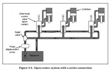
Read section 2 and pay particular attention to figure 2-4

Capture.JPG

Here's a link to another good explanation of power beyond.
Hydraulic valve power beyond or high pressure carry over
 
   / Please explain PB #17  
I was under the assumption that PB was that foul smelling stuff your sprayed on rusted bolts to break them loose. Goes to show you what I know.....:D
 
   / Please explain PB
  • Thread Starter
#18  
Here's a link to the Army field manual for hydraulics FM 5-499. It is in PDF format. I suggest everyone download this manual (its just a bit too big to upload to TBN) and keep it on your computer for reference. Download it now, because the location tends to change from time-to-time, but you can always find it by googling "army FM 5-499".

http://www.derijcke.com/dl/manual.pdf

Read section 2 and pay particular attention to figure 2-4

Thanks, good documentation. I looked at your references but have not read the full manual.
From what I see it looks like PB is just a built in T.


View attachment 458295

Here's a link to another good explanation of power beyond.
Hydraulic valve power beyond or high pressure carry over
Thanks, good documentation. I looked at your references but have not read the full manual.
From what I see it looks like PB is just a built in T.
This is why I am confused.
 
   / Please explain PB #19  
Here's a link to the Army field manual for hydraulics FM 5-499. It is in PDF format. I suggest everyone download this manual (its just a bit too big to upload to TBN) and keep it on your computer for reference. Download it now, because the location tends to change from time-to-time, but you can always find it by googling "army FM 5-499".

http://www.derijcke.com/dl/manual.pdf

Read section 2 and pay particular attention to figure 2-4

View attachment 458295

Here's a link to another good explanation of power beyond.
Hydraulic valve power beyond or high pressure carry over

Thanks a bunch Moss.
 
   / Please explain PB #20  
Thanks, good documentation. I looked at your references but have not read the full manual.
From what I see it looks like PB is just a built in T.
This is why I am confused.

Yeah, I used to think that too. I figured that any return to the tank was just another return to the tank.... but its not.

For example, my machine has high pressure to the steering valve. There's two exits on the steering valve. One is low pressure and dumps back to the tank, and the other is a high pressure power beyond port off the steering valve that supplies high pressure to the FEL valve bank. The only exit from the FEL valve bank is low pressure back to the tank.

So, all high pressure fluid passes right through the steering valve to the FEL valve UNTIL I turn the steering wheel. Then some (or all) high pressure fluid goes to the steering cylinders, then out the low pressure port back to the tank. Any unused high pressure fluid that the steering valve doesn't use continues on to power the FEL valve bank. If I crank the wheel all the way to either side, using all the high pressure available to the steering valve, the FEL valve won't function until I back off the steering a bit. That's because its downstream of the steering valve. So in my machine's case, steering has priority over FEL functions.

Make sense?
 

Tractor & Equipment Auctions

2014 RANCO ANVIL END DUMP (A47001)
2014 RANCO ANVIL...
NEW Wolverine 5 Way Push Blade (A48289)
NEW Wolverine 5...
New Bulk Lot Of 5/16 Chain Slings (A48289)
New Bulk Lot Of...
Case 16' Offset Disc (A47369)
Case 16' Offset...
PARTS (A47001)
PARTS (A47001)
2017 KENWORTH T680 TANDEM AXLE SLEEPER (A45676)
2017 KENWORTH T680...
 
Top