You are using an out of date browser. It may not display this or other websites correctly.
You should upgrade or use an alternative browser.
You should upgrade or use an alternative browser.
Pot Question
- Thread starter Damifino
- Start date
- Views: 2205
/ Pot Question
#11
workinonit
Elite Member
Definitely low wattage. I would think there would be some number on that shell somewhere. If not you will need to locate a drawing for that grinder.
Damifino
Gold Member
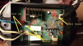
I have looked all over pot...no numbers, nothing. I guess my next move is to gut it out and see if any values are on pcb. I cut the wires on the back half and tabbed together. Got nothing throughout range.
Next step is guttin it out, will keep you posted and thanks for everyone's guidance.
Next step is guttin it out, will keep you posted and thanks for everyone's guidance.
CobyRupert
Super Member
Can you measure the speed pots resistance?
If near zero, it’s probably used with AC voltage. If, not near zero, and variable, it could be ac or dc.
Last ditch would be, with 3 wires unhooked, to start up machine and measure what the voltages are between the 3 wires.
Or look to see what voltage the power supply to the circuit board is.
I think 0-5vdc, 0-10vdc, 24vdc, 24vac are common “control” signal voltages.
Damifino
Gold Member
CobyRupert
Super Member
I should of said what is the voltage supply ON the circuit board, instead of TO the CB. It’s probably not 110V.
I mean the voltage in the wire to the pot.
Typically you can think of a pot as an impedance (~resistor) connected across 2 wires. For example: Let’s say one wire is 10 volts, the other is 0 volts (a ground reference). The impedance of the potentiometer now has 10 volts across it. The potentiometer moves/connects (“taps”) the third wire somewhere between the two ends of that impedance depending on where you turn the dial.
So with the dial turned all the way down, the third wire sees 10 volts. With it turned all the way up, third wire sees the 0volts. With dial turned in the middle, 3rd wire sees 5 volts, 1/4 turn =2.5 volts, 3/4 turn = 7.5 volts etc.. Always between 0-100% of the “control voltage” being used.
So, in this example, the input to the circuit board on the third wire is somewhere between 0-10V. The other two wires supply the 10V and 0V reference.
You need a potentiometer rated for the correct control voltage.
If you have that, almost any potentiometer will give you the 0-100% input on the 3rd wire.
CobyRupert
Super Member
Damifino
Gold Member
Thanks Coby, so if I do what your post #14 instructs, this should be the info I need?
CobyRupert
Super Member
Well...without specific info on the existing potentiometer or the circuit board (do you have any info on the circuit board / variable speed drive?), it’s the only way I can think of to get information that gets you closer to a replacement.
Short answer: yes.
Short answer: yes.
CobyRupert
Super Member
Do you think your grinder uses same pc board and pot as this one?:
http://s3.amazonaws.com/dpec/assets...96/23-196 6-Inch Grinder Parts List Rev 9.pdf
http://s3.amazonaws.com/dpec/assets...96/23-196 6-Inch Grinder Parts List Rev 9.pdf


