Beechwood said:
Kent, If I add two new wheel motors all I would do is take the output side of the oem motor and tie it into the input side of the new motor then take the oem return line and tie it into the output side of the new motor, creating a closed loop system like the original configuration. Once the new system is recharged and equilized then all pressure will be the same . As JJ said the pump is only going to put out so much pressure regardless of how many motors you have. But the pump output pressure might have to be reset( increased ) for the extra motors. Correct?
Beechwood, I was talking about my planned mod to my PT-425, which is actually described back in the archives here as Stray's mod. Stray started down the path of designing a two-speed implementation, based simply on routing the hydraulic circuits and using valves to switch between the two different circuits. He began work on a test configuration that would be a permanent low-speed system. That is what I plan on doing -- converting my system to low-speed, high-torque by changing the plumbing from two parallel circuits (each with two motors on it, in series) to 4 parallel circuits with each motor on its own circuit. (Note that PT at one time offered a two-speed setup, according to some posters here...)
With your proposal, if you plumb it the way that you describe, it will still have only two parallel circuits with now 3 wheel motors in series on each circuit. There would theoretically be no increase in torque, and no decrease in speed other than the added resistance of the extra plumbing. The pressure would remain essentially the same (though the resistance of the extra plumbing might increase it by a small, inconsequential amount).
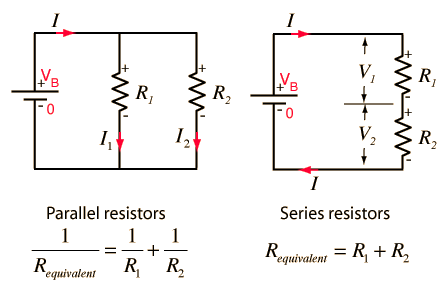
The best way for me to understand hydraulic systems is by using the analogy of a DC electrical circuit, which I do understand, where voltage = hydraulic pressure and amperage = volume of fluid. If you change from a parallel to a series circuit, you double the amperage but cut the voltage in half, and vice versa... The same thing happens in a hydraulic system -- changing from series to parallel circuit increases the pressure and decreases the volume.
It's much easier to mentally picture if you consider the drive pump a fixed displacement pump, instead of variable. That way, you can mentally picture the pump as being a "constant" in the circuit at any given RPM...
In this DC circuit example, consider the resistors (R1 and R2) as wheel motors. You currently have two separate circuits of two wheel motors in series. I'm planning to convert to 4 parallel circuits, with each supply and return line coming back to separate 4:1 manifolds at the pump.

