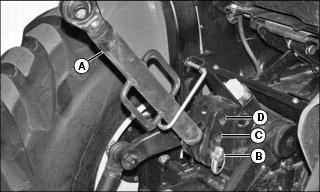
I couldn't find anything about keeping the upper link in any particular relationship to the drive shaft. Other then what I posted previously, the manual just describes how the upper link is used for fore-aft leveling of an implement.
Here's a link to the manual, if you'd like to look:
omlvu23778_i0=
=========
You guys got me going to the manual. I researched my snowblower manual not the Kioti manual. My blower is a Martin/meteor 60" rear. According to Martin they want to see that both angles (top link and drive shaft) are at a minimum and the larger the angle the shorter the life of the life of the PTO (they must be referring to Universal joint alone)
They use a 60 H.P. tractor and rear blower as an example and suggest parking the unit on a level surface like a garage floor and include this metric,
A=PTO height at tractor 18 1/2" (figures represent my unit)
B= PTO height at blower -14 1/2"
C= A - B 4"
L=cross center length of shaft with blower at working position (center of U.J. to center of U.J) 24"
Subtract B from A (A-B=C) in my case that figure was 18 1/2 - 14 1/2 = 4
Divide L by C 24/4 =6
That figure of 6" then goes to the table supplied by Martin and now becomes the F Factor. The below list represents Martins table and refers to angle of drive shaft as determined by above numbers
F Factor Angle degrees 1 st number below is F factor
6 10
3.75 15
2.75 20
2.15 25
1.75 30
The lower the degree column the better and as you can see my particular tractor used as an example reveals the blower drive is at 10*. So far as relationship of top link to drive shaft they claim the top link in working position (snowblower)should be as level as possible and the drive shaft should be as close to parallel with top link as you can get. This is about the best I can determine and it looks like my drive shaft slopes a bit downward. It's boound to with that 10 degree angle. Basically the book leaves me hanging at that point.
Sorry about these charts they never post the same way you type them.
YMMV
rim
