MikeOConnor
Silver Member
- Joined
- Dec 16, 2002
- Messages
- 173
- Location
- Western Wisconsin
- Tractor
- Two Power-Trac 1850s (preferred for mowing and grapple-bucket clearing type work on really steep hills). Kubota M680 for snowblowing, grading, bucket.
Hi gang,
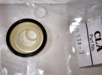
I'm fixing blown seals in my accumulator today and would normally call Terry about this one -- but it's Saturday and they're not around.
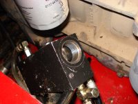
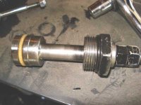
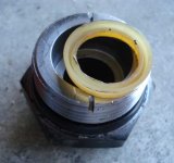
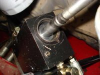
I've attached a photo of where I'm at -- I've removed the big spring and the seal fitting. What you're looking at is the piston. Which doesn't budge when I pull on it.
Hence my question for somebody who's pulled this unit apart. Should I just pull harder, or should I be relieving hydraulic pressure, or is there a retaining nut I should be removing, or... what?
No biggie -- I can ask Terry on Monday, just thought I'd see if anybody's got the word to the wise today.
I'm fixing blown seals in my accumulator today and would normally call Terry about this one -- but it's Saturday and they're not around.
I've attached a photo of where I'm at -- I've removed the big spring and the seal fitting. What you're looking at is the piston. Which doesn't budge when I pull on it.
Hence my question for somebody who's pulled this unit apart. Should I just pull harder, or should I be relieving hydraulic pressure, or is there a retaining nut I should be removing, or... what?
No biggie -- I can ask Terry on Monday, just thought I'd see if anybody's got the word to the wise today.

 The accumulator may be totally different, but this kinda' brings back memories of near disaster when someone at the track tried to mess with a nitrogen-charged mono-shock. It blew parts under considerable force around the race pits. His sheepish reply was that the unit had no warnings on it