Question for draftsmen and pattern makers

   / Question for draftsmen and pattern makers #1  

WinterDeere

Super Member
Joined
Sep 6, 2011
Messages
5,419
Location
Philadelphia
Tractor
John Deere 3033R, 855 MFWD, 757 ZTrak; IH Cub Cadet 123
Here's one for all you draftsmen and pattern makers out there. Yeah, I mean you, @dadohead, @dodge man, @wawajake, and @Grumpycat... among others.

I need to indicate the clocking of a circular hole pattern on the end of a cylinder, relative to a radial hole pattern on the cylindrical face. Or put otherwise, in the attached drawing snippet, I need to indicate the clocking tolerance of the 8x Ø.136 drill pattern in the view on the left, to the clocking orientation of the 16x Ø.1640 THRU holes in the view on the right. I assume I snap a datum on one and use a location tolerance on the other, but not having ever properly learned GDT (I'm EE, not ME), I'm not sure the best way to properly note this.
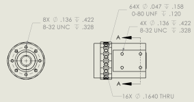
1738896784453.png

I intend to specify the tolerance in degrees rotation, not inches displacement.

Thanks!
 
   / Question for draftsmen and pattern makers #2  
Here's one for all you draftsmen and pattern makers out there. Yeah, I mean you, @dadohead, @dodge man, @wawajake, and @Grumpycat... among others.

I need to indicate the clocking of a circular hole pattern on the end of a cylinder, relative to a radial hole pattern on the cylindrical face. Or put otherwise, in the attached drawing snippet, I need to indicate the clocking tolerance of the 8x Ø.136 drill pattern in the view on the left, to the clocking orientation of the 16x Ø.1640 THRU holes in the view on the right. I assume I snap a datum on one and use a location tolerance on the other, but not having ever properly learned GDT (I'm EE, not ME), I'm not sure the best way to properly note this.

View attachment 2644773

I intend to specify the tolerance in degrees rotation baixar snaptube, not inches displacement.

Thanks!
I have been reading through the Tape_EBOOK and the user manual for Seamly me.

I can see that when Seamly Me opens and you click on new file, you can then see measurements as well as Information. Within “information” there is a field to indicate a pattern making system. I don’t quite understand what the pattern making system would be used for. Does that have a function other than indicating/reminding that you are going to use a certain system to make a pattern? Is it supposed to link to those sizing charts on the relevant pages from the books, or is it supposed to automatically check the known measurements that are used in the system?
 
   / Question for draftsmen and pattern makers
  • Thread Starter
#3  
I have been reading through the Tape_EBOOK and the user manual for Seamly me.

I can see that when Seamly Me opens and you click on new file, you can then see measurements as well as Information. Within “information” there is a field to indicate a pattern making system. I don’t quite understand what the pattern making system would be used for. Does that have a function other than indicating/reminding that you are going to use a certain system to make a pattern? Is it supposed to link to those sizing charts on the relevant pages from the books, or is it supposed to automatically check the known measurements that are used in the system?
Thanks for de-railing the thread, on the very first reply. :rolleyes:
 
   / Question for draftsmen and pattern makers #4  
Wow! That's quite an engineering problem. I used to teach GD&T at Deere but haven't thought about it in 10 years!

So you only want to call out the timing (clocking) of the 8x pattern with the 16x pattern? You don't want it to control location, orientation, and form of either pattern?

A couple things: you can dimension the pattern any way you want using basic dimensions (rectangular box around dims). You can even be redundant because they are actually locating the theoretical tolerance zone of the feature. Your GD&T callout then details what that tolerance zone looks like.

The second point: the best way to think about a GD&T callout is to envision a physical fixture that checks just what you want (sometimes check fixtures  are made). Give it some thought. Once you know the fixture, the callout describing the GeoTol can be made.

In dealing with two patterns, I'd probably reference the same primary, secondary, tertiary datums for each pattern and make a "true position" callout for each. This indirectly does what you want and allows you to detail location, orientation, and form for the patterns as required.

One last point: please know that even those who use GD&T on a regular basis don't always get it right. It often leads to confusion and phone calls. If you simply want to clock one pattern to the other... maybe a simple +- dimension would be best.... but let's start with what you think the check fixture looks like.
 
Last edited:
   / Question for draftsmen and pattern makers #5  
This is more technical that I am used to and I do not fully understand the scope but why can't you simply put a note for the tolerance and specification on the side ? this is usually common practice.
 
   / Question for draftsmen and pattern makers #6  
Here's one for all you draftsmen and pattern makers out there. Yeah, I mean you, @dadohead, @dodge man, @wawajake, and @Grumpycat... among others.

I need to indicate the clocking of a circular hole pattern on the end of a cylinder, relative to a radial hole pattern on the cylindrical face. Or put otherwise, in the attached drawing snippet, I need to indicate the clocking tolerance of the 8x Ø.136 drill pattern in the view on the left, to the clocking orientation of the 16x Ø.1640 THRU holes in the view on the right. I assume I snap a datum on one and use a location tolerance on the other, but not having ever properly learned GDT (I'm EE, not ME), I'm not sure the best way to properly note this.

View attachment 2644773

I intend to specify the tolerance in degrees rotation, not inches displacement.

Thanks!
A-A is not shown? The flat surface (surfaces?) in A-A needs to be established in relationship to the radial and axial holes. I'm having trouble seeing the flat surface with 4x of .136 round. Not so sure as to the flat surface and the diameter it is on. But I don't believe the above is complete.

I think I would make a B-B view sliced through the 16x .1640 to show their relation to the 8x of .136 round. And that needs to be tied to the flat(s) of 4x .136. This might all fit in A-A.
 
   / Question for draftsmen and pattern makers #7  
Here's one for all you draftsmen and pattern makers out there. Yeah, I mean you, @dadohead, @dodge man, @wawajake, and @Grumpycat... among others.

I need to indicate the clocking of a circular hole pattern on the end of a cylinder, relative to a radial hole pattern on the cylindrical face. Or put otherwise, in the attached drawing snippet, I need to indicate the clocking tolerance of the 8x Ø.136 drill pattern in the view on the left, to the clocking orientation of the 16x Ø.1640 THRU holes in the view on the right. I assume I snap a datum on one and use a location tolerance on the other, but not having ever properly learned GDT (I'm EE, not ME), I'm not sure the best way to properly note this.

View attachment 2644773

I intend to specify the tolerance in degrees rotation, not inches displacement.

Thanks!

I’m also a little confused about the exact question but I think I understand. You cut a “cross section” through where there are 8 holes. I’d just dimension the angles between the holes at 45 degrees. I’d then cut additional cross sections as needed to show the additional holes. You may need to show an additional top view with cross sections too.
 
   / Question for draftsmen and pattern makers
  • Thread Starter
#8  
Hey guys, the confusion is all my fault. I'm an EE, who took plenty of drafting classes in high school and college, but my only jobs in drafting were all civil and landscape, so never really got into GDT. Since what I do is very "mechanical", I have to create a lot of drawings, but following one old machinist's advice that "any GDT symbol on a drawing instantly doubles the cost of the part", I've always avoided it.

Anyway, going back to dadohead's point that's been at least partially echoed by a few others, I did not mean to say that the pattern locations are uncontrolled. In fact, they're controlled relative to the centerline of the cylinder. But because we've never had trouble with our fabricator holding sufficiently-tight tolerances on location of these patterns relative to the primary cylinder bore, we don't specify anything beyond the .005" implied global tolerance for all features taken from the imported 3D model.

The clocking issue has come up, because there are actually hole patterns on both ends of the part, and there is extra fixturing cost involved in clocking the pattern on one end of the feature relative to the other. It is usually the case that I need the hole pattern on one end of the part clocked accurately to these Ø.164 radial thru holes, but the pattern on the other end can be "visual only". The machinist has to call me for each new part design we submit, and say, "okay, which patterns need to be clocked accurately to which other patterns?"

What I ended up doing on this drawing, just to get this one submitted for bid, is to put a note "CRITICALLY-CLOCKED TO Ø.164 THRU HOLES" on that pattern of #8-32's, and then put a similar note "VISUAL CLOCKING ONLY" on the hole pattern on the other end. This helps to keep GDT off the drawing, and is clear as day to the one fabricator who's been making these parts to me, but will require discussion and clarification with any new fabricator bidding the job in the future.

That's probably good enough for now, but I'm still interested in how it would be "properly" done, by a real trained draftsman.
 
   / Question for draftsmen and pattern makers #9  
following one old machinist's advice that "any GDT symbol on a drawing instantly doubles the cost of the part", I've always avoided it.
Lol
Yeah... it depends on the supplier. Deere's production parts come in and go to the CMM room (coordinate measuring machine), GD&T programmed, and 30 pc studies run to show capability. This is repeated if any change occurs in the process. We calm the tolerancing way down for prototype parts though.... for the reasons you state above.

Placing in the note section makes sense here:

Pattern X to be timed with pattern Y: +- 2 deg

Simple and captures your intent.
 
   / Question for draftsmen and pattern makers
  • Thread Starter
#10  
Yeah, only about 1 out of 10 of my parts go on the CMM, and given they're all flavors of a particular type, the machinist already knows the reference planes from which the coordinates are being taken. So we get away without resorting to GDT.

Many of my other parts have very critical dimensions, but are specifically designed such that all critically-toleranced operations can be performed from a single setup, such as shell milling and then boring any tightly-toleranced dowel hole locations in the same setup. The CNC's they run today are so incredibly accurate, that their finished tolerances come down almost exclusively to changing setups (indexing to a new face when part is turned) and to plating thicknesses.

Machine part designers used to have to work a lot harder than we do today, to hold very tight tolerances. It's rare I get anything back from the shop today, where the diameter is out more than half a thou (.0005"), or location of features performed in the same setup are off by more than a few tenths, at least as long as I stick with 6061 and keep my aspect ratios reasonable. Some of the long and skinny turned parts, especially those done in copper instead of 6061, can be a little more challenging. But even there, the machine programing allows them to pretty easily comp out the flex in the part for a given cut depth and travel speed, to where they're still holding close to ±.001 diameters.
 

Tractor & Equipment Auctions

AGT 3pt or SS Seeder (A47809)
AGT 3pt or SS...
Mini Excavator Fixed Position 3-Tooth Thumb Attachment (A45336)
Mini Excavator...
2012 Caterpillar 621H (A45336)
2012 Caterpillar...
John Deere Pallet Forks (A47809)
John Deere Pallet...
QUICK COUPLER (A47001)
New Holland #28 Silage Blower (A47809)
New Holland #28...
 
Top