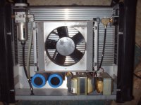
Here's the other side of the Hypertherm, showing the large heat sink, cooling fan. On the upper left is the air inlet with regulator and filter. On the upper right is the pressure sensor and pressure gauge connections. At the bottom are a couple of power capacitors, and a couple transformers.
You are using an out of date browser. It may not display this or other websites correctly.
You should upgrade or use an alternative browser.
You should upgrade or use an alternative browser.
Resurrecting a dead plasma cutter...
- Thread starter tomrscott
- Start date
- Views: 26420
More options
Who Replied?
/ Resurrecting a dead plasma cutter...
#21
johnbilt
Silver Member
Looks Good.
Have you had a chance to apply power and check some voltages yet ?? Do you have the owners manual with the input voltage connection diagram ?? I assume you have are setting it up for 240VAC.
John
Have you had a chance to apply power and check some voltages yet ?? Do you have the owners manual with the input voltage connection diagram ?? I assume you have are setting it up for 240VAC.
John
johnbilt,
I haven't begun actually working the problem yet for two reasons. I want to get a better schematic if I can. I am supposed to be getting a service manual for the correct version for my serial number in the mail this week. Also, this Friday I am having lunch with a friend that is bringing me some part samples I've ordered for some of the electronic components that I think could be bad.
I guess the other reason too is that my projects have to move slow to fit into a pretty crowded schedule; school at night, family, kids, wife, work, chores. etc.
Finally, I have needed an excuse to get the workshop better organized, and the 240V 50A circuit in the shop was behind stacks of stuff that needed to get organized before I could get at the circuit. I did manage to get that started last weekend. Its not entirely organized to my satisfaction, but I can now get at the 240V circuit. I also want to run a 240V 20A circuit in order to split it into two legs of 120V 20A for running the compressor and other power tools from the same end of the shop. I've got the wire and hardware to do that so it might get done this coming weekend. Also need a to run a dedicated circuit for my lathe at the other end of the shop.
Now that I have some good pictures of the board to document all of the wiring, I will begin by disconnecting things from the PCB and labeling anything that might not get connected back the same way so I can pull the PCB out of the box and put it on the bench. Once I get the board out, I will pull one leg of a lot of 2 pin parts to test them, and probably pull a couple transistors to see if I can find anything obviously dead. No point in powering it up until I've done some obvious checks. I don't have any doubt that there is a problem, no point in powering it up and maybe making things worse if there is a chance I can find an obvious problem and fix it the easy way.
This is not an easy circuit to test "hot" given the voltages present. I'm confortable with doing that as I've had some experience with very high voltage in things like ham radio tube amplifiers. Doing it safely though requires some HV probes that I don't really have but could improvise if it comes down to it. Safety with high voltage requires physical separation, thick insulation, avoiding putting yourself into the circuit (htey used to say "put one hand in your pocket") and avoiding allowing yourself to ever become the best path to ground. Nothing to be trifled with. A lot of very experienced old-time amateur radio "ham" operators used to be killed while working on high voltage tube amplifiers. One of my old home-built "boat anchors" has an 800V circuit. These kind of voltages don't just tickle, in the right circumstance they can kill you real dead. /forums/images/graemlins/frown.gif
Long story short. As anxious as I am to get it working, I am also willing to be patient and go slow, one way or another, I'm going to plasma-cut some steel soon. /forums/images/graemlins/smirk.gif
I have also had an offer of some assistance from a friend who is the shop manager at an industrial heavy equipment contractor. I guess he has a couple techs that work for him who work on the really big electric power stuff all the time and could probably easily troubleshoot this thing.
I may actually get some stick welding in before I get the plasma cutter up and running. I've been reading and studying all I can get my hands on in preparation for lighting an arc the first time I get a chance. Lots of welding ideas already. I'll soon have some hydraulic cylinders that need new ends welded on, got them ordered last week.
As I slowly make more progress on this project, given the interest, I'll be sure to post updates here.
/forums/images/graemlins/smirk.gif
johnbilt
Silver Member
Tom
Gotcha - I try to balance the work schedule, family, home fixes, chores, hobbies....., as well. Good luck !
I checked my Hypertherm 1000 manual last night and it really does not show much of any detail concerning the component level of the system. I work in the electronic engineering field, but am more familiar with control circuitry and systems engineering, as opposed to specific HV power supplies.
It may be beneficial to break the circuit path at the output of the power supply to isolate the functions on the board. You can always solder back a new jumper after test and repair. I'm sure you know this, I'm just typing out loud....
If I can power up my unit and check voltages or functions for you for troubleshooting comparisons, just ask.
A plasma cutter is a great machine to have. I paid the big $$ for it, but it sure does the job when you need it, like nothing else can.
Have fun and good luck. I like projects where I can learn something new.
John
John,
Well I got the Hypertherm Service Manual for my Powermax 600 today. The schematic is about the same as the one I had. Unfortunately it primarily shows the off-PCB field-replaceable modules and very few details of the on-circuit-board components. That is a bit disappointing, but not a complete surprise.
The manual does have some very useful system functional theory-of-operation description. It also contains some voltage and resistance checks and some checks for the IGBT modules and a few other things.
I will probably begin troubleshooting by going through their diagnostic process to see what it reveals. I gather from the shop I acquired it from that the problem appears to be on the circuit board, but maybe the result will give me a bit more clue about where to look on the board.
I really do wish that they would provide a complete board schematic. I wonder if any other vendors do? After I get into the troubleshooting a bit, if I get stuck, I will try to see if I can manage to get through to an engineer to talk about the circuit.
For one thing, I am very curious whether they have chosen a replacement for the FUJI IGBT that is so hard to get. There are many high quality alternatives that are much more readily available for about 1/10th the cost, so I have to believe they have picked one to replace this part with in newer versions.
I am pretty well committed to getting this thing cutting. Just in the few weeks since I began looking for a plasma cutter I've already come up with a whole list of uses for it beyond the initial task of cutting out some wheel weights for my 790.
johnbilt
Silver Member
Yep, sounds like a good learning experience.....Maybe you'll get lucky and not have to deal with the expensive IGBT components.
The service manual must be setup for a shop to replace modules only. Hard to follow the circuit path without a full schematic.
John
The service manual must be setup for a shop to replace modules only. Hard to follow the circuit path without a full schematic.
John
John,
Yes I believe the manual is -- as you suggest -- set up for a shop to only work with FRMs (Field Replacable Modules). I suspect they figure the typical welder repair shop doesn't have much electronic circuit theory expertise, and that circuit board rework skills might be poor. If it takes more than a screwdriver and wrenches to fix, it had better come back to the factory. If they published more data and thus encouraged PCB rework, it might result in more problems than it solved, and could even lead to liability issues. This kind of practice often comes down to liability concerns these days.
I hope to actually make a little bit of progress troubleshooting it this weekend. The weather looks like it might be good. My welding and cutting site of choice is the concrete driveway right in fron of my workshop, so dry weather is quite helpful. Otherwise I have to go inside and the ventilation is not as good. I would like to get at least an initial run through with it to know what I am going to be up against. After collecting some initial data, if it doesn't look promising, I would like to take that information and see what help the factory will give me. There are a series of resistance and voltage measurements the service manual gives, and some diagnostic LEDs that may or may not reveal anything useful.
I also did a bit of design work this week on a circle cutting jig for the cutter torch when I had some time to kill. I think I've got a workable and flexible design. It would give me both a circle cutting jig and a straight-edge guide as well, from the same torch fixture, probably very similar to the kit they sell, except a lot cheaper.
I found another alternative to the discontinued and expensive to acquire FUJI IGBT, this one from IXYS who has a reputation for making VERY robust IGBTs. I found a part that is rated for a bit higher voltage and current but very similar in DC characteristics. Every part I have found with similar or better DC characteristics are faster than this FUJI part (probably the reason it is discontinued). Assuming the increased speed doesn't cause a problem, they will cause far less power loss, and in a similar circuit function won't get as hot or be stressed as much. The IXYS part is an IXGH16N170. There is also an IXGH10N170 that is probably also an adequate replacement. I hope to be getting some of these in a week or so if needed. Part of what makes this analysis difficult is that FUJI didn't provide very much data on their part. IXYS is wonderful about providing lots of data, but there are only a few parameters that are rated similarly and can actually be compared between the two. In any case, if I were redesigning the Hypertherm circuit to replace the FUJI part, the IXYS parts are the transistor I would use. /forums/images/graemlins/wink.gif
johnbilt
Silver Member
Hi
Sounds like you have done a fair amount of research. I took a glance at the data sheet for the IXYS part. It appears that you are on the right track. I won't try to guess what the critical parameters are in regard to timing because I don't know the operational configuration in detail.
A few thoughts......The gate drive appears to have a wide range (Vge) and affects the series voltage drop (Vce). Is this spec similar to the Fuji part ?? What does the drive circuit of the Hypertherm provide ?? This is assuming that the IGBT is the point of failure and needs replacement.
You may find additional info from one of the cnc plasma companies. Two that I have found are plasmacam.com and torchmate.com. They both recommend the Hypertherm units for their cnc tables. Perhaps they would offer some tips or schematic info in regard to the failure mode of your H600.
Once you apply power, you'll have some real data to work with.
John
Well, I finally got the electrical work done in my workshop to test the plasma cutter. The previous owner had a 50A 240Vac outlet, but it was a different receptacle than my welder and plasma cutter required, so I needed to redo it, and while I was at it, I decided to add a local disconnect and decided to wire up both the old receptacle and the new one to be more flexible. I also needed a 20A 120VAC circuit to run my compressor next to the plasma cutter since it won't run with the voltage-drop of an extension cord. I ran 10AWG three wire with ground from a 20A 240VAC breaker, but hooked it up as two phases of 20A 120VAC to give me lots of power tool capacity with very little voltage drop. I already had the 10AWG wire on hand.
So..., air filter plumbed, compressor charged up, 50A 240VAC wired up, and Hypertherm service manual in hand, I decided to sit down and go through the diagnostics in the service manual.
I checked all the resistance checks and didn't find anything amiss, so I switched on the Hypertherm's three pole breaker, and the fan started spinning up, the top LED for input power came on, and then "CLICK" the breaker snapped back off with the "Low Line Voltage" LED lit yellow momentarily, and a moment later, the fan shut off.
I did that enough more times to get through the voltage checks and could see that it was firing up looking good for a brief moment, but something was shutting it off???
Looking at their troubleshooting guide for that symptom didn't quite help, it didn't list that exact combination of symptoms. It did mention the circuit breaker snapping off as soon as you switch it on, but not with the Low Voltage LED lit. It suggested the cause could be Over Voltage, or shorted components. But in the brief instant when it was first coming on, I could briefly measure roughly the correct voltages everywhere I should, so it didn't really act like a dead short, and I knew the 240VAC was dead on, and besides, the "Under Voltage" light was lit?
I studied the schematic and then something jumped out at me: Right at the top of the drawing was a little rectangle labeled "W14" indicating a winding that was labeled to indicate it was used to detect "Over Voltage", it showed a dotted line to the circuit breaker indicating that it could trip the breaker, and it had a note that said "208/240VAC Unit Only." There is not enough circuit detail in the schematic to understand how that fault condition is detected, but it connected to J5 on the circuit board. I could see that J5 had a jumper that was connected across the third unused pole of what is a three pole circuit breaker. On three phase units, all three poles are used for power phases, but on 240VAC single phase units like mine that third pole is used somehow to trip the breaker if the system detects overvoltage... Hummm...
I said to myself, "The system acts like a safety circuit is shutting it down, I know it is not connected to the wrong voltage, what can it hurt to disconnect the overvoltage trip? The three phase units don't bother with an over-voltage safety circuit, and I don't have any higher voltage to connect it to anyway. What could it hurt to discnnect that jumper?"
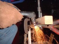
I pulled J5, clicked on the breaker, the fan came on, the power LED came on, and ... NO CLICK! The "OK" LED came on with no error LEDs! Eureka! I put on my welding mask, grabbed the torch and held it up to my test piece and IT CUT LIKE A HOT KNIFE THROUGH BUTTER, WITH SPARKS FLYING!!! I realized later that I had been cutting at the lowest power setting 20A. Did a couple more cuts and took the picture in the previous posting with the camera on self timer. The first time I tried, I had finished cutting before the self timer went off. I had to trip the shutter and wait till it started beeping fast to begin the cut!
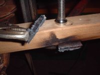
I've attached here a picture of the second cut I made. Pretty ugly, I have to learn how fast to move it and get a smooth cutting surface so it doesn't hang up and skip. I also realized as you can see in the picture that I wasn't holding the torch tip perpendicular.
Tomorrow I'll call the Hypertherm Service Department and see if they won't help me replace whatever is wrong. It should be pretty simple to find now that I've got this much figured out. Something obviously wrong with their overvoltage detect circuit. Frankly, if they won't help me with it, I'll just used it with this circuit disabled and not worry about it, but I have a hunch they'll help me get it fixed correctly.
I now have a 40A Plasma Cutter!!! /forums/images/graemlins/grin.gif /forums/images/graemlins/grin.gif /forums/images/graemlins/grin.gif
So..., air filter plumbed, compressor charged up, 50A 240VAC wired up, and Hypertherm service manual in hand, I decided to sit down and go through the diagnostics in the service manual.
I checked all the resistance checks and didn't find anything amiss, so I switched on the Hypertherm's three pole breaker, and the fan started spinning up, the top LED for input power came on, and then "CLICK" the breaker snapped back off with the "Low Line Voltage" LED lit yellow momentarily, and a moment later, the fan shut off.
I did that enough more times to get through the voltage checks and could see that it was firing up looking good for a brief moment, but something was shutting it off???
Looking at their troubleshooting guide for that symptom didn't quite help, it didn't list that exact combination of symptoms. It did mention the circuit breaker snapping off as soon as you switch it on, but not with the Low Voltage LED lit. It suggested the cause could be Over Voltage, or shorted components. But in the brief instant when it was first coming on, I could briefly measure roughly the correct voltages everywhere I should, so it didn't really act like a dead short, and I knew the 240VAC was dead on, and besides, the "Under Voltage" light was lit?
I studied the schematic and then something jumped out at me: Right at the top of the drawing was a little rectangle labeled "W14" indicating a winding that was labeled to indicate it was used to detect "Over Voltage", it showed a dotted line to the circuit breaker indicating that it could trip the breaker, and it had a note that said "208/240VAC Unit Only." There is not enough circuit detail in the schematic to understand how that fault condition is detected, but it connected to J5 on the circuit board. I could see that J5 had a jumper that was connected across the third unused pole of what is a three pole circuit breaker. On three phase units, all three poles are used for power phases, but on 240VAC single phase units like mine that third pole is used somehow to trip the breaker if the system detects overvoltage... Hummm...
I said to myself, "The system acts like a safety circuit is shutting it down, I know it is not connected to the wrong voltage, what can it hurt to disconnect the overvoltage trip? The three phase units don't bother with an over-voltage safety circuit, and I don't have any higher voltage to connect it to anyway. What could it hurt to discnnect that jumper?"
I pulled J5, clicked on the breaker, the fan came on, the power LED came on, and ... NO CLICK! The "OK" LED came on with no error LEDs! Eureka! I put on my welding mask, grabbed the torch and held it up to my test piece and IT CUT LIKE A HOT KNIFE THROUGH BUTTER, WITH SPARKS FLYING!!! I realized later that I had been cutting at the lowest power setting 20A. Did a couple more cuts and took the picture in the previous posting with the camera on self timer. The first time I tried, I had finished cutting before the self timer went off. I had to trip the shutter and wait till it started beeping fast to begin the cut!
I've attached here a picture of the second cut I made. Pretty ugly, I have to learn how fast to move it and get a smooth cutting surface so it doesn't hang up and skip. I also realized as you can see in the picture that I wasn't holding the torch tip perpendicular.
Tomorrow I'll call the Hypertherm Service Department and see if they won't help me replace whatever is wrong. It should be pretty simple to find now that I've got this much figured out. Something obviously wrong with their overvoltage detect circuit. Frankly, if they won't help me with it, I'll just used it with this circuit disabled and not worry about it, but I have a hunch they'll help me get it fixed correctly.
I now have a 40A Plasma Cutter!!! /forums/images/graemlins/grin.gif /forums/images/graemlins/grin.gif /forums/images/graemlins/grin.gif
Attachments
PILOON
Super Star Member
Reading your first post, at the price you paid, I guess you'll be losing a lot of sleep due to guilt! LOL.
Guess it is being at the right place at the right time.
I too will lose sleep.
Went to a flea market this PM and came across a combination 36" band 10" disk sander setup, cast iron construction (probably Grizzley maybe Delta (lable was missing)) c/w good motor that I picked up for $40. ($30us) . It was missing the 'idler roller' for the band section but otherwise complete.
A simple shaft, 2 brgs and a drum and it'll be good as new.
(And I have a lathe to turn the missing idler drum!)
As I said, right time right place!
Shucks anybody can pay full price.
Them's the real fun purchases.
Hey I did not even dicker on the price.
johnbilt
Silver Member
Excellent. Glad to hear the problem was not so dire. Always glad to hear of a fellow tinkerer done well.
John
John
John,
You and me both.
You know, its funny, I was prepared for the worst, expecting it to be real tough to find without a proper schematic. It seems like if I am very careful and prepare thoroughly, often the job goes more smoothly, not necessarily because of anything I've done, but almost as a providential reward for my diligence and discipline.
Now I just need to finish the circle cutting jig I've designed and get a dry day to cut out my tractor wheel weights outdoors.
I also need to start practicing with the stick welder and learn how that works. In a few days I'll getting some hydraulic cylinders that need new ends welded on. I want to get enough practice on other stuff that I can do a half-way decent job of it.
I'll post more pics as I make progress.
Thanks for everyone's moral support!
/forums/images/graemlins/smirk.gif
