Rustyiron
Super Member
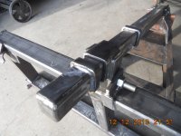
I've been making converted p/u truck snowplows for tractors & SS's for a while using this design that allows for float (normal) action along with down pressure. Notice the tube in tube with the welded stops on what could be called the "top link". If you can't see in the pics, you curl in the bucket function so that it hit's the stops and raise's the plow, and "dump" until you hit the stops for d/p.
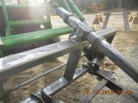
On this particular plow I gave it 12" of plow motion before it hit either of the stops. You position the frame (bucket curl out) to a mid point between the stops, ( 3" each way to the stops) giving you 6" of travel down, and 6" up. You need to provide a pivot point at each end of this tube for the slight movement through it's arc, and it need's to be rugged. The geometry on this plow/frame worked out that each inch of travel on the diag. tube gave 2" of plow movement. The tube is 2x2x.25 wall, and the rectangular tube(s) at the loader are 2x3x.25 wall. Thought it might help someone.
On this particular plow I gave it 12" of plow motion before it hit either of the stops. You position the frame (bucket curl out) to a mid point between the stops, ( 3" each way to the stops) giving you 6" of travel down, and 6" up. You need to provide a pivot point at each end of this tube for the slight movement through it's arc, and it need's to be rugged. The geometry on this plow/frame worked out that each inch of travel on the diag. tube gave 2" of plow movement. The tube is 2x2x.25 wall, and the rectangular tube(s) at the loader are 2x3x.25 wall. Thought it might help someone.