hazmat
Elite Member
- Joined
- Feb 12, 2002
- Messages
- 4,051
- Location
- West Newbury, MA & Harrison, ME
- Tractor
- Kubota L5460HSTC
For Russ (and other's who might be interested) - sorry it took me so long.
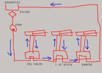
The attached diagram shows a typical flow of hydraulic fluid thru a compact tractor.
For those interested in adding remote hydraulics for a top & tilt or whatever, there are two ways to do it.
#1 buy the valve from your tractor dealer. Generally speaking you take a cover off the three point hitch valve & add the new one to the "stack". There have been a couple good photo-essay's of this process on tbn Here's one for a New Holland
#2 buy the "power beyond" kit from your dealer - this is the tubing/hoses to attach a backhoe to your tractor. This gives you a supply and return fitting to which you can plumb your own valve or valves.
Hope this helps.