User circuit DK45 Cab

   / User circuit DK45 Cab #1  

kiotiken

Veteran Member
Joined
Aug 29, 2011
Messages
2,344
Location
Dunrobin, Ont
Tractor
2012 Kioti DK45 HST Cab
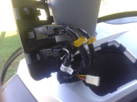
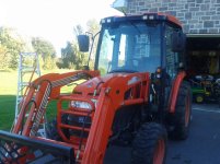
I'm adding LED work lights to my DK45 cab. They are 18W and I'm installing 4 in the front and 4 facing the back. Looking at the wiring harness at the switches, there's one unused connector. Is that from the "users power1" or "user power2" circuits?

I'm total clueless when it comes to electrical wiring, I was planning to copy what they did for the existing work lights. Should I run new wires back to the fuse box or can I use the single unused connector to feed two switches, one for the front and one for the back?

Thanks


ForumRunner_20130929_135446.png
 
   / User circuit DK45 Cab #2  
I'm adding LED work lights to my DK45 cab. They are 18W and I'm installing 4 in the front and 4 facing the back. Looking at the wiring harness at the switches, there's one unused connector. Is that from the "users power1" or "user power2" circuits?

I'm total clueless when it comes to electrical wiring, I was planning to copy what they did for the existing work lights. Should I run new wires back to the fuse box or can I use the single unused connector to feed two switches, one for the front and one for the back?

Thanks


What i did was just add a new lighted switch in the empty spaces of the switch consul and run it back to the spare fuse block on the left side of my seat. Mine doesnt have the unused wiring harness next to the existing switches like yours does.


View attachment 339085

if your hooking up 8 x 18 watts of lights to a single switch. youll need to wire in a solenoid or contactor. Then the switch would only need to power up the closure circuit of the solenoid, which will be in the miliamp range. The line side that is powering the lights will have to come from a source that can supply the total amperage draw of the lights.

am i correct in assuming your thinking of adding 1 lights, each 18 watts?. if so thats aprox 12 amp draw. So of theres a spare 15 amp circuit available youll have no issue at all.

Its possible to find a 12 amp toggle switch i suppose, but its common practice to wire the lights to a contactor, then control the on off function by powering up the contactor.
 
   / User circuit DK45 Cab #3  
Actually, you have 2 - 6 amp draws. Assuming you want to operate the front and rear lites the front and rear lites separately. Given that, you said you were not an electrical guy, I am so, I'll explain. I'll apologise now if you already know all this.

The lites for the front, need to be wired in parallel not in series (daisy chain). I can draw you a picture if required. The rear are done the same way.

Eash lite is 18 watts.

18 watts / 12 volts = 1.5 amps X 4 lites = 6 amps (same for the rear)

GRS is correct, you should use a relay to switch the power to the lites, but with two strings of lites (1 front, 1 rear), you need two relays, each controlled by its own switch. Effectively, the switch operates the relay and the relay operates the lites.

Grey area ahead! With 6 amp draw, you could wire from fuse to switches to lites directly. Boom, done.
 
   / User circuit DK45 Cab
  • Thread Starter
#4  
Thanks guys. For some reason, 12v wiring just flies over my head. What I was hoping to do is use the extra circuit Kioti leaves for us to feed two switches, one for the front and one for the back. I'm not really sure how contactors or relays work but I was thinking that since it is a 20A circuit, I would be fine since all my lights are only 12.

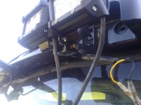
So since I really don't understand what I'm doing and I don't want a repeat of PickeringChris experience, I took another look at what was there and decided to ditch the OEM lights and replace them with the LED's. I modified the brackets a little, changed the way the LED mount on their brackets so that I could mount two lights on one bracket and I'm off to the races. I figure the old ones were 55W, or 110W for the front and the new ones are 18W X 4 for the front or only 72W total, so I should be OK, right? Anyway, I roughed it all in and installed it loosely and just went out to try them out in the dark. HOLY CRAP !!!! :eek: They're bright, and I only have the fronts done so far. It works well since I have two pointed a little lower and two pointed up for distance. I have a slightly different plan for the back, but I'll do the same and ditch the OEM lights.

So, is that unused connector (bottom of the first pic I posted) the 20A circuit they leave for us?

20130929_162244.jpg
20130929_162258.jpg
20130929_162304.jpg
 
   / User circuit DK45 Cab #5  
Looks awesome! :thumbsup:

Now I gotta go shoppin'. :laughing:
 
   / User circuit DK45 Cab #6  
The white connector on the harness you accessed in your cab is marked user or something similar. It can be used for a work light or whatever so long as you stay within the amperage rating of the fuse that it's wired to. The most basic difference between AC and DC voltage is that DC is direct current, fed from a 12 volt supply, your battery to a hot and ground returns to actual earth, via the chassis and tires. household wiring is a hot, neutral and a ground which also makes it way back to earth through a ground rod driven into the ground. Most off road light kits come with a wiring harness and a relay to allow one to wire them up fairly easily. The advantage you have with your LED lights is more light with less amp, (current) draw off your battery. And less heat generated, longer bulb life, and just better all round look too. The fuse acts like a house breaker- when there is too much draw, of current through the wires in a circuit, the breaker, or in the case of 12 volt DC, the fuse breaks(opens) and allows the wires to not burn up. The relay helps reduce the current in parts of the wiring and allows the lights to be controlled by a switch in the harness which closes the circuit through the relay and lights your lights.

If you put a space between each pic you upload, between each attachment they will have some room between each and be easier to view on the page...

Nice job; now use some dielectric grease to seal the ends of those bullet connectors. Ideally you'd use heat shrink tubing to make a waterproof seal on each.
 
   / User circuit DK45 Cab
  • Thread Starter
#7  
Looks awesome! :thumbsup:

Now I gotta go shoppin'. :laughing:

Thanks, and yes, you do! Everybody says what a difference LED lights make over the factory lights so my expectations were high. I was still amazed at the difference.
 
   / User circuit DK45 Cab
  • Thread Starter
#8  
The white connector on the harness you accessed in your cab is marked user or something similar. It can be used for a work light or whatever so long as you stay within the amperage rating of the fuse that it's wired to. The most basic difference between AC and DC voltage is that DC is direct current, fed from a 12 volt supply, your battery to a hot and ground returns to actual earth, via the chassis and tires. household wiring is a hot, neutral and a ground which also makes it way back to earth through a ground rod driven into the ground. Most off road light kits come with a wiring harness and a relay to allow one to wire them up fairly easily. The advantage you have with your LED lights is more light with less amp, (current) draw off your battery. And less heat generated, longer bulb life, and just better all round look too. The fuse acts like a house breaker- when there is too much draw, of current through the wires in a circuit, the breaker, or in the case of 12 volt DC, the fuse breaks(opens) and allows the wires to not burn up. The relay helps reduce the current in parts of the wiring and allows the lights to be controlled by a switch in the harness which closes the circuit through the relay and lights your lights.

If you put a space between each pic you upload, between each attachment they will have some room between each and be easier to view on the page...

Nice job; now use some dielectric grease to seal the ends of those bullet connectors. Ideally you'd use heat shrink tubing to make a waterproof seal on each.

grs, rmorey, CM, I appreciate the info. I did look up relays and contactors to try and learn something for next time. I'm still confused about them and why they're needed (not that I doubt any of you at all) and why a switch can't handle 6 or 12 V, after all, household switches can handle 15V. Do the factory switches simply control relays somewhere before they hit the lights, both front and back?

I was also having a hard time understanding why there are 3 wires from the switches. Rick mentioned that you need to wire them in parallel, so I was kind of assuming there's a hot wire for each light on the circuit and one ground wire that's shared. Now that you guys are talking about relays (and assuming Kioti is using one), I'm confused over why there are 3 wires again. Wouldn't you have power to the relay (2 wires), a switch connected to the relay (again, two wires) and 3 wires running from the relay to the two sets of lights?

CM, for you, I'll start adding a space. I thought I was being nice by at least breaking them on to separate lines! Those bullet connectors have something in them from the factory, not sure if it's dielectric grease. I can't use heat shrink tubing since the lights have to be disconnected in order to open the roof panel of the cab (along with the radio antenna). Kioti did a poor job IMO with access to the roof, not only do you have to disconnect the lights and radio, you have to remove the grey light bar at the front of the cab.
 
   / User circuit DK45 Cab
  • Thread Starter
#9  
Oh ya, I've been smelling coolant anytime I have the heat turned up. Obviously hasn't been a burning issue over the summer, but since I finally had the roof open, I took a closer look. I was expecting a line to be leaking but found a big pool of coolant around what I'm pretty sure is a mixing valve. It seems to leak (and I figured it out from the smell) only when the heat is turned on full or close to it. I kept feeling around the ceiling looking and feeling for coolant to be leaking through, but it was caught in an area of the roof and seems to have stayed put up there.
 
   / User circuit DK45 Cab #10  
Ken here is a simple explanation for the why and where to use relays. Relays are often used for two reasons.

Reason one is that relays often have large contacts that can handle large currents, and be controlled by switches or micro controllers that can only handle small currents.

Think large currents (a lot of amps) will require large wires to safely carry that current. Small currents can be safely handled by little bitty wires. So by using a small switch or an electronic module of some kind that can only deal with small currents to control a relay that can handle large currents you now have an easy method to control those large currents and still have small switches or microprocessors doing the controlling.

OK, now on two the second reason. The second reason is controlling large currents from a remote location. Instead of bringing large wires back to a switch that is rated for large currents for example back into your cab then back out to where the current is needed, why not put a relay out on the firewall to control those large currents? Lets control if from a little switch or micro controller located somewhere else remotely.

The benefits are you save on the amount of large wire, you save on having to have a large switch rated to control that much current and you save on the losses of running the large wire long distances instead of a short distance.

Furthermore in the case of the Micro controllers there is not a good way to make them able to even handle those large currents at all.

Now for a simple explanation of how the relay works inside. The relay has a coil of very small wire inside that when a very small current is passed through this wire it makes a magnetic field.. In other words it is an electromagnet. The magnet that is created when current is flowing is near a piece of steel called the pole piece. Attached to this piece of steel is a moving copper contact to carry high currents. There is also a non moving copper contact to mate with the moving contact to carry this current on and out of the relay body.

When the magnet attracts the piece of steel and attached moving copper contact, it moves toward the fixed contact and they mate together and the high current flows through these contacts.

When the small coil current is removed by the switch or micro controller the coil is no longer magnetic and the steel pole piece moves back to the relaxed position by pressure from a small spring. When the relay is energized by the coil, it has enough power to overpower the small return spring pressure.

Now you know how relays work inside, and a couple of reasons to use them:)

James K0UA
 

Tractor & Equipment Auctions

8Yd Dumpster (A44571)
2013 UTILITY 53X102 DRY VAN TRAILER (A43004)
2013 UTILITY...
Ryobi Sliding Compound Miter Saw (A44391)
Ryobi Sliding...
More info coming soon! (A44571)
More info coming...
1982 De Lorean Tug (A44391)
1982 De Lorean Tug...
2014 INTERNATIONAL PROSTAR + TANDEM AXLE SLEEPER TRUCK (A43003)
2014 INTERNATIONAL...
 
Top