lens12
Veteran Member
- Joined
- Apr 7, 2000
- Messages
- 2,127
- Location
- Dixon, Il
- Tractor
- ford 9700, tw30, massey, jd2030 jd4010, yanmar F60d, ym330d, ym276d,ym226d,ym186d, ym2000, ym155
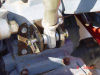
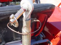
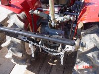
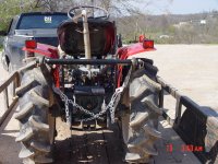
The YM1602 never came with a 3 point. I'm leery of screwing in a pin. I've seen them break out. The best way to install the lower arm pins is to run a rod through the holes in the hitch. Make 2 brackets with a hole for the rod to go through that can be fastened to a couple bolts where the axle housings bolt to the rearend. This is how the 3 point kit was installed on the YM1502.