YM240D front axle leak repair progress post

   / YM240D front axle leak repair progress post
  • Thread Starter
#11  
Since you are going to be checking your backlash with the housing put together here is how I would do it. I would put a bolt in one of the stub axle holes that the wheel bolts to. That should be the appx diameter of the front drive gear. With your indicator fastened to housing with magnet base, c-clamp or whatever, then put the point of the indicator against the installed bolt. You can then measure the movement back and forth while feeling the gear contact. You need to be measuring at a distance close to the diameter of the front drive gear. Anything further will give a larger reading, anything closer will give a smaller reading. Hope this makes some sense to you.

Do you not recommend checking backlash with the housing off? (it is currently assembled with the housing off)
 
   / YM240D front axle leak repair progress post #12  
I guess I am lost here. I thought everything was assembled except the stub axle. What gears are you wanting to check backlash on?

Back again, I am not sure you would get an accurate backlash reading without the lower front gear case being installed. The spindle shaft would not be located in the bottom bearing and just to much possibility of something moving. I am not there and have never done this, only stating what I feel based on drawings and lifes experiences. I am going to look in my I&T manual to see if I am missing something.

And again. The I&T manual is certainly not detailed in the procedure. If you feel the spindle shaft and stub shaft are held ridged enough without the lower front gear case installed then you can use the outer perimeter of the stub shaft gear to put your indicator against. I&T calls for .004 to .006".
 
Last edited:
   / YM240D front axle leak repair progress post #13  
Heh, I had similar feelings about prussian blue. Found and ordered Dykem on Amazon, should come by Friday.

I noted that I need proper tools, but... researching how to use dial indicator on this type of gear and how to use it to measure backlash caused more confusion rather than clarified things for me. :confused::confused::confused: Any pointers/youtube videos/articles with good visuals are appreciated.

My shop manual has illustrations for this type of gear, but not in a section about front end (I also don't have that section in my service manual). It talks about things being too close or too far, but I didn't know how to use the dye correctly until I read How to Set up Your Rear Gear Correctly RacingJunk News a few days later, so I did not quite grasp the meaning of what I saw at the time. This weekend we try again :D

OK. You're progressing on the dyes, that's good.
Dial indicators measure small movements of at the end of an arm by transmitting that movement via gears and shafts to a clockface dial. Hence the name.
Generally the dial indicator is mounted rigidly to something like a table or vise and the moveable arm placed against what is to be measured
There are two types of dial indicators, which one you use depends on what kind of motion you are measuring and how you can get set up to measure it.

The first type has a has a spring-loaded telescoping rod that reports movement of the tip of the rod toward or away from the dial face. I think that is the type in your video. It typically has a range of several inches and will measure in resolutions of thousanths of an inch = .001. It is commonly used in mechanical shops. To use it on a gear you might tape of glue some little piece of metal to the outer edge of the larger gear and rest the tip of the rod against it. Or maybe reach down with the tip and try to put it directly on the curved surface of the bevel gear. Is that what they are doing in the video? How weird if true. I can't tell what they are thinking they are doing in that video!!


The other type of dial indicator has a rigid (not telescoping) rod, but at the tip of that rod is another much smaller arm set a an adjustable angle to the rod. It reports movement of that smaller arm. In general, this type can fit in more places than the first telescoping type, but has a smaller range of motion. It will typically measure a full scale of less than a tenth of an inch in units such as +/- .015" or sometimes +/-.030" or +/- .050. But the resolution can be as small as in tenths of thousanths of an inch = .0001"
This type of dial indicator is more likely to be found in a machine shop instead of an mechanic's shop. It is actually more versatile in how you can use it, but delicate to set up.

Both types of dial indicator are commonly mounted to a magnetic base that is clamped onto any convenient piece of steel. Older types used C clamps.

That reminds me that when measuring backlash you need to figure out just where the shop manual wants you to measure that backlash. You are actually measuring rotational degrees - just as you mentioned previously. How many inches those rotational degrees span can be a function of how far away the tip of the dial indicator is away from the gear faces themselves. If the shop manual say backlash of only a few thou, it is probably right at the gear faces themselves. In that case, set the shims for the right dye pattern and double check that by doing just what everyone has said: give it some clearance, definitely not tight at all, and don't give it sloppy clearance. No need for the dial indicator in that case unless you just want to get one and play with it.
luck,
rScotty
 
   / YM240D front axle leak repair progress post #14  
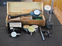
Here is a selection of mechanical dial gauges for precision measurement and setting up backlash. One tends to accumulate these things. Today most measurement is via laser. These old mechanical style gauges last forever and with luck can be picked up cheap at used tool stores. I bought these in the 1960s - and most were used at the time.

As several others here have posted, after you have set up a few things you will get used to the "feel" of backlash and then the dial gauges become almost superfluous. One simply substitutes feel for measurement - as in "some play, but not too much". For the experienced person that says it all. But I still like to use dye to confirm that the engagement of the gears is roughly across the center of the mating teeth. The shop manuals and that video you posted show examples of tooth engagement. It's an art as well as a science.
rScotty
 

Attachments

  • IMG_8433.JPG
    IMG_8433.JPG
    637.8 KB · Views: 92
   / YM240D front axle leak repair progress post
  • Thread Starter
#15  
I guess I am lost here. I thought everything was assembled except the stub axle. What gears are you wanting to check backlash on?

Back again, I am not sure you would get an accurate backlash reading without the lower front gear case being installed. The spindle shaft would not be located in the bottom bearing and just to much possibility of something moving. I am not there and have never done this, only stating what I feel based on drawings and lifes experiences. I am going to look in my I&T manual to see if I am missing something.

And again. The I&T manual is certainly not detailed in the procedure. If you feed the spindle shaft and stub shaft are held ridged enough without the lower front gear case installed then you can use the outer perimeter of the stub shaft gear to put your indicator against. I&T calls for .004 to .006".

Trying to check the backlash on the gear on stub axle. Didn't take the entire front end apart as the rest of that area appears ok/untouched.

I assembled everything on the stub axle with housing cover, and attached the without the knuckle housing. Stuff (gear, shims, bearing, spacers) on the stub axle + the housing cover (bearings, seal) seems to be firmly held in place by the axle nut. In this stage, I will try to get it close. Then put the whole thing together, re-measure the backlash and adjust if necessary. I don't want to keep disassembling and re-assembling the gear case, and I think this approach will minimize that.
 
   / YM240D front axle leak repair progress post #16  
Good plan. :thumbsup:
 
   / YM240D front axle leak repair progress post
  • Thread Starter
#17  
So, I am back!

And just realized that there were 4 shims on each side (2 were very stuck together): 2 x 0.2mm and 2 x 0.3mm. That added up to 1mm!! And still left what feels like a lot of backlash (still don't have a tool or correct service manual with directions to measure this properly). I have a plethora of shim choices now, so I am wondering if adding (a theoretical number) enough shims to add up to 2mm sounds reasonable?
 
   / YM240D front axle leak repair progress post #18  
Without seeing or feeling the backlash I have no idea. Just add some and see what happens, may have to do this several times.
 
   / YM240D front axle leak repair progress post #19  
So, I am back!

And just realized that there were 4 shims on each side (2 were very stuck together): 2 x 0.2mm and 2 x 0.3mm. That added up to 1mm!! And still left what feels like a lot of backlash (still don't have a tool or correct service manual with directions to measure this properly). I have a plethora of shim choices now, so I am wondering if adding (a theoretical number) enough shims to add up to 2mm sounds reasonable?

I think that 2 mm is reasonable. As Winston say, you may have to assemble it many times. Shims don't have any upper limit, they just gradually become known as "parallel face ground washers" as they get thicker. But I've seen them considered as "shims" all the way up to about a quarter inch (6mm) thickness. Basically I would shim to whatever it takes for the engagement backlash to be loose ... but small.

I like to think of the thickness (width) of the ball bearing shell itself as being part of the shim thickness - and it's a pretty thick shim itself, often being in the 15 to 20 mm range. Designers use bearing width as part of the shim calculation since bearing width is very, very flat & consistent.

Don't forget any paper gasket thinkness. Thin paper gaskets can be as thin as .1mm thickness (.004") and the thick black fiber gaskets with the punched out holes can easily be .5mm (.020"). Hmm... Are there any paper gaskets in there? I've forgotten just what combination of gaskets and seals Yanmar used.
Maybe it's time to think about gasket goo, though.

It would be interesting to track how the sealing of that bevel gear front axle has evolved from the time that Yanmar first brought it out as a Yanmar exclusive - until today when it is the type of front steering axle used by most every 4wd tractor on the market.
luck, rScotty
 
   / YM240D front axle leak repair progress post #20  
Anything other than "snug but free" is serious overkill, when considering a maximum speed of 7-8 mph. Backlash is mostly concerning "whine" at speed.
 

Tractor & Equipment Auctions

2015 Ottawa Yard Spotter Truck - Cummins Diesel, Allison 6-Speed, Hydraulic Air Fifth Wheel (A52748)
2015 Ottawa Yard...
2011 PETERBILT 367 TRI-DRIVE WITH TAG (A52472)
2011 PETERBILT 367...
2018 WACKER NEUSON CORPORATION DBA WACKER NEUSON LTV6 LIGHT TOWER (A52472)
2018 WACKER NEUSON...
4K SAND SEPARATOR (A52472)
4K SAND SEPARATOR...
2022 K-Z Sportsmen 260BHSE 28ft T/A Travel Trailer (A51694)
2022 K-Z Sportsmen...
2018 JLG 3246ES 32FT. Scissor Lift (A51691)
2018 JLG 3246ES...
 
Top