YW-6 Backhoe Problem

   / YW-6 Backhoe Problem #41  
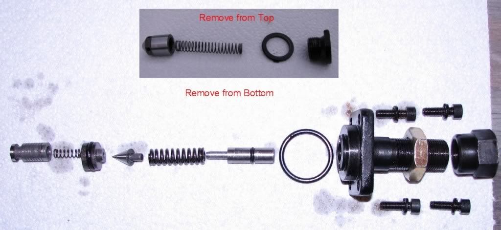
Bob is exactly right, I was using the term "ball" generically. It is a plunger with a beveled sealing surface. Here is a pic of the parts in mine. If you zoom in on the hole all the parts go into, you can just see where the diameter reduces way down in there. This is the inner seat that the beveled sealing surface of the check"ball" rests on.. Down thru that smaller diameter hole lies the top of the relief valve assembly...

 
   / YW-6 Backhoe Problem #42  
This may help in the discussion. This is from the relief valve on a JW03.
RonJ
JW03ReliefValvePieces.jpg
 
   / YW-6 Backhoe Problem #43  
This photograph is excellent. If and when I have to check for debris in the relief valve, do I remove the top or bottom or both?
 
   / YW-6 Backhoe Problem #44  
This photograph is excellent. If and when I have to check for debris in the relief valve, do I remove the top or bottom or both?

Easy enough to do both... The bottom relief assembly comes out with the removal of the 4 smaller screws. The top part comes out with a very large blade standard screwdriver...
 
   / YW-6 Backhoe Problem #45  
I didn't read back through this whole post, but if you take off the bottom - be sure that you are using a pressure gauge for necessary adjustment after putting it back together.
RonJ
 
   / YW-6 Backhoe Problem #46  
I didn't read back through this whole post, but if you take off the bottom - be sure that you are using a pressure gauge for necessary adjustment after putting it back together.
RonJ

If you disassemble using the 4 small flange screws, you shouldn't need to re-adjust, as you are not doing anything to the actual adjuster screw/bolt. That was my experience when I initially disassembled mine but I had a gauge in place to take before and after measurements to know this:)
 
   / YW-6 Backhoe Problem
  • Thread Starter
#47  
If you disassemble using the 4 small flange screws, you shouldn't need to re-adjust,


I'll have to remember that. However, in this case the adjuster backed it's way completely out so even if I didn't take it apart it needs to be readjusted.

Thanks again for all the advice guys! This is what I love about Tractorbynet, lots of friendly advice and less of the nonsense seen on other forums.


Now if one of you knows how to replace the control unit without a nightmare of adapters....
 
   / YW-6 Backhoe Problem #48  
Replacing the control valves would be a big project with all the adaptors as well as new hoses converted to JIC. Maybe there's enough to justify a thread on improving the existing valve?

I had to add various shims to get the looseness out of the linkage, in fact, it was so loose one of the projections actually lost contact with the adjacent plunger.

I find if I run the RPM too high the control is really jumpy. Around 1,000 RPM it's pretty manageable.

I've read where users have inserted different devices (orifices) to slow down certain functions.
 
   / YW-6 Backhoe Problem
  • Thread Starter
#49  
I'm well aware of the mess of replacing a control on the Jinma. I replaced the loader control and added an extra spool to control a grapple. I'm pleased with how it turned out but with the adapters, it was EXPENSIVE.

I was hoping someone would speak up and say hey TractorX supply has a $5 adapter what will let you connect the Surplus Center control in 10 minutes....

So much for wishful thinking. : )
 
   / YW-6 Backhoe Problem #50  
Yep, because of the ORFS hose ends, replacing the valve would be a big project, unless you could find a quality valve with 18MM ports. Then the existing hose ends and adapters would bolt right on... Another option might be re-machining an existing valve to the metric thread...

It sure would be nice to have individual load checks on each circuit:)

The only real area mine is jumpy is in boom swing. It takes a comprimise in engine RPM/pump flow to get acceptable control out of the boom and acceptable speed out of the rest of the circuits. The boom swing cylinders are the smallest cylinders in the system and have the shortest lever arm. they are also only single acting. This and the available pump flow make the boom move real fast. On mine, the metric to ORFS adapters on the swing circuit already have restricted orifices in them(1/16") but the boom can still move pretty fast. I had one of my swing cylinder end packings unscrew, so I pulled the whole cylinder to retighten it and to get a look at it. I finally found the small hole that allows the front of the single acting cylinder to pass air. It is a trunion mount cylinder, but it would not be that difficult to add a front hydraulic port to the cylinder and add crossover hoses to convert them to double acting. That would add 30-40% to the ammount of fluid flow required for a given boom swing... it would also probably add 30-40% more power to the boom swing with both cylinders pushing/pulling... Wether that would be a bad thing, I am not quite sure yet. I am contemplating it. If it dosn't work, I guess I can always screw in an air filter and plug the supply side ports to put it back the way it was...
 

Tractor & Equipment Auctions

2006 FREIGHTLINER CST120 (A53843)
2006 FREIGHTLINER...
2008 FORD F350 XL SUPER DUTY DUMP TRUCK (A51406)
2008 FORD F350 XL...
SHOP FAN (A53843)
SHOP FAN (A53843)
2018 DRAGON PRODUCTS 130BBL VACUUM TRAILER (A53843)
2018 DRAGON...
2 - BOXES (A53843)
2 - BOXES (A53843)
TORO MBTX 2500 STAND-ON CONCRETE BUGGY (A51406)
TORO MBTX 2500...
 
Top