See.. It wasn't 11 days between posts this time. Only 9.

Where were we.. Ah yes, the non-rod end of the side links.
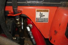
With the
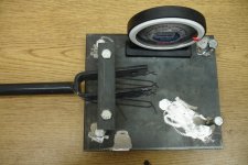
BX22 I had to consider where to locate the cylinder ports so that the ports and fittings wouldn't bend up the fenders when the hitch is raised. Take a look at the first picture and you'll see where the top port and 90 degree fitting are in relation to the fender.
The trick to making sure you will clear the fender is to consider the worst case scenario. The ball end in the lift arms will allow the clevis to rotate some, so you need to rotate it to towards the fender then figure out the safe angle for the ports in relation to the clevis end. Sounds difficult doesn't it..
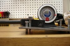
Picture two to the rescue! Found it online somewhere. Print it out as multiple pages per sheet and it will print a handful of correctly sized protractors for a 2" cylinder. If they are still not the right size, try to save it as a .jpg and use a photo editor to resize it. Or you can google for a different one.
So how do you use the protractor? Just center it on the bottom of the clevis end such that either 0/180 or 90 is square with the open side and stick it there with a piece of tape (number side up). Raise the lift arm as high as it will go. Now pin the clevis end onto the lift arm and twist it to towards the fender. Eye ball the point where it clears the fender and mark it with a pencil or something. This will be the OUTSIDE of the cylinder port.
Hold the clevis end with protractor onto the non-rod end of the cylinder and line up the mark with the correct side of the port. Now make a mark on the cylinder for the point that is
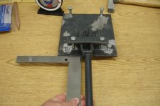
squared with the clevis end. For example, when I taped my protractor to the clevis end, I set the 90 degree to be square with the open side of the clevis. The mark I made on the protractor after holding it up to the fender was on the 65 degree point. So once I lined up my 65 degree mark with the cylinder port, I marked the 90 degree point onto the cylinder. (
Please note that when I did it I guesstimated the center point of the port when I marked the protractor. I later determined that the side of the port would have been the more accurate & easy way to go. So where the last picture says the clevis is rotated 25 degrees from the ports, it is 25 degrees from the CENTER of the port. Your number will be different if measuring from the side of the port)
Once you have the mark on the cylinder, draw a line across the middle of the non-rod end of the cylinder using the mark as your reference. When you go to weld the clevis on to the cylinder, this line should run through the middle of the open side of the clevis end.
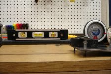
You can use the same jig as was used for the rod-end work. Do the same setup to figure out the angles, adjust the height, and tack weld the end onto the cylinder. The only difference here is you need to pay attention to where that mark on the cylinder is in relation to the open side of the clevis end.
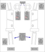
And BE SURE you have the correct cylinder before you weld. The
right cylinder rod end clevis angles to the left and to the front, with a non-rod end angled towards the right. The
left cylinder rod end clevis angles to the right and front of the tractor, with a non-rod end angled towards the left. I screwed this up twice.. Yes, twice.
This is why you TACK weld.
Now that you have both ends tacked to the cylinder, carefully pin it to the lift arms and lower arms. I say carefully because it is just tacked and cannot support much load w/o bending or breaking the welds. Now make sure everything fits like it should. If you need to change it, break or grind off the tack welds and adjust as needed.