OK, now let's get back to the drive train.
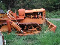
In the first photo, I have just removed the bell housing from the driveline
tunnel. The pump side of the HST is visible, as well as the forward/reverse
control rods, which are attached to the swash plate control. The swash
plate angle determines how much oil is pumped by the pump, and in which
direction. This Eaton HST uses no separate charge pump; the power
steering pump mounted to the front of the engine does double duty as
a charge pump. The charge pump is necessary to pre-charge the inlet of
the piston pump, as well as to provide make-up oil for the substantial amount
used by the HST to lubricate the piston slippers.
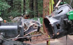
In the 2nd photo, the HST is out. The pod-shaped section in the center
is the HST motor housing, terminated with the main drive spline shaft. You
can see the PTO drive above it, which is also the shaft that runs straight
thru the pump.
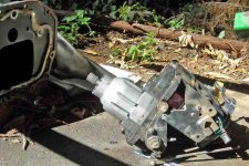
In the 3rd photo, you can see inside the tunnel, which contains the three
drive shafts (PTO, MFWD, and main) and gallons of oil. To get all of these
shafts to line up properly, JD is considerate enough to give us an access
port on one side....good thing! The red bulkhead in the back of the tunnel
supports all of the range shift gears and shafts. You can also see the
horizontal shaft that shifts the MFWD on and off.
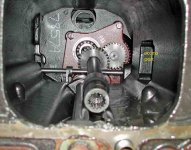
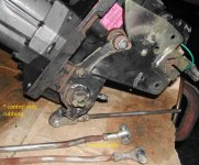
The 4th photo shows a closeup of the HST controls. The rods are terminated
at both ends with swiveling connections (aka Heim joints). I will replace
them as they were all getting a little loose. You can also see three places
where the control rods rubbed on various components. This is due to a
sloppy repair job that was missing a couple of washers and an improperly
installed neutral switch. I will eliminate the switch since it offers little
value or safety, and will eventually fail again. You can also see a weld
repair if you look closely at the upper control rod. It is very important that
these rods are tight and well lubricated so that the HST control will not
bind (a common complaint).
")