J_J
Super Star Member
- Joined
- Sep 6, 2003
- Messages
- 18,928
- Location
- JACKSONVILLE, FL
- Tractor
- Power-Trac 1445, KUBOTA B-9200HST
What does RPS mean? I don't have one on my machine. Someone said something about a charge pump valve.
What does RPS mean? I don't have one on my machine. Someone said something about a charge pump valve.
What I wonder is whether it worth installing a 10 micron filter on the upstream side. It would filter all of the oil eventually...
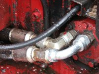
Hey bob, My filter is upstream. Between the RPS and the black steel block.
Now, I could have messed up when changing a filter and got dirt into the system.
Also, I think that Ksimolo found out that the filter we share (he has an 1850) is a 25 micron and not a 10 (I have never looked).
The only system on my PT that is filtered prior to the pumps is the wheel motors. But as it is a somewhat closed loop system, how much is being filtered is in question. Although, the supply pipe is big (1" to the filter - 3/4" coming out).
Carl
This is from memory
One goes to the brakes, one goes to steering and one goes to lift and tilt. And I think one goes to the Draft control. The brakes line then somehow feeds back from the brake to the hydraulic treddle.
I have a hose on the top that goes to overflow.
Peters should be the same... Ksimolo's is identical to mine, so he may know better... I am just not near the PT anytime soon...
You have the hydraulic treadle! My machine doesn't. So--it seems that the differences in the hydraulic system are related to the hydraulic treadle.
Another question--does your machine have the Brake tender system and if so are the brakes external disk brakes that are spring applied and hydraulically released?
PS--I purchased my machine new from PT in May of 2003 and it does not have the hydraulic treadle. That strongly suggests that your machine was built after May 2003.