Conversion Factor for 3PH load capacity

   / Conversion Factor for 3PH load capacity #21  
Spyder, you seem to have it all figured out, please enlighten me if I am wrong.

Hitch ratings are devalued, lessening with distance behing attachment. That's a fact in the real word bore out by both theory and what can be realized in practice.

What you seem to be going on about is the fact that no matter how far behind the attachment the load is, the tractor sees the same load. I'll grant you that. One will notice that the weight transfers to the rear tires as the load is extended behind, with the rear gaining the same amount that the front loses. Something about a moment happening there.

The vertical force component (for a given load) bore by the lift arms is a function of the top link angle (to vertical) and distance beyond the lift arm attachment. That's a fact. It works for the case of parallelogram too.

If you keep extending a load out on your boom pole, how far out can it go before there is a failure in the hitch linkage? I'll bet if the top link doesn't fail in tension, the lower link will fail in compression at some point. Or, the front wheels come off the ground. That's a fact.

Where am I wrong so far?

On the cantilevered thing, think of your perfect parallelogram supporting the cantilever. I hope you didn't think that I thought the parralelogram could support anything without the lower link being controlled.
 
   / Conversion Factor for 3PH load capacity #22  
Spyder, you seem to have it all figured out, please enlighten me if I am wrong.
[[Hitch ratings are devalued, lessening with distance behing attachment. That's a fact in the real word bore out by both theory and what can be realized in practice.]]

What you seem to be going on about is the fact that no matter how far behind the attachment the load is, the tractor sees the same load. I'll grant you that. One will notice that the weight transfers to the rear tires as the load is extended behind, with the rear gaining the same amount that the front loses. Something about a moment happening there.
[[The vertical force component (for a given load) bore by the lift arms is a function of the top link angle (to vertical) and distance beyond the lift arm attachment. That's a fact. It works for the case of parallelogram too.]]

[[If you keep extending a load out on your boom pole, how far out can it go before there is a failure in the hitch linkage? I'll bet if the top link doesn't fail in tension, the lower link will fail in compression at some point. Or, the front wheels come off the ground. That's a fact.]]

Where am I wrong so far?

[[On the cantilevered thing, think of your perfect parallelogram supporting the cantilever. I hope you didn't think that I thought the parralelogram could support anything without the lower link being controlled.]]
Good!
There are a few points to look at that you have highlighted in you summary:
[[One reason for this is the near impossibility of setting the 3ph up in perfect //ogram form on all implements. Others you brought out well [[here]].]]

Lets talk about it in the perfect sense. [[ Think more about that //ogram - starting at the tractor body and completed by the implement hookup...If all weight of the load is concentrated at the hookup point it bears straight down on the eyes. Tension and Compression in the links is extremely small and relates to the angle of the links to horizontal. When you extend the load behind the hookup point that same load presses down on the eyes. The torque required of the tractor hydraulics doesnt change but the torque back tipping the tractor does. T&C forces in the opposing links transfer this torque directly into the tractor body. The opposing forces balance.
Extended load 3 cases; 1]Movable links Horizontal - take the horizontal T&C forces directly to the tractor mount points. No force on verticle links, 2]Movable links up - take the T&C forces generated by the overhung load. These inputs are purely horizontal but T&C comes into play in the vertical links to preserve the form. As the top link is pulled it tries to move the assembly down due to its angle, but is balanced by compression of the lift link making an equal effort to rise, 3]Movable links down... Youve got the idea.:)]]

[[No, I didnt think that, but I thot that somehow you thot the lifting force needed would increase as overhang increased even if actual assembly weight didnt. Torque consolidated in the earth moorings has to take the the increased strain along with the associated T&C elements of the structure.]]

Thanks for taking a serious look at this.
larry
 
   / Conversion Factor for 3PH load capacity #23  
Not getting into any calculations, I just happened to have my owners manual on the desk to look up capacities for my tractors upcoming first service.
It says "three point hitch Max. lift force:
at lift points 970 kg 2139 lbs.
24 in. behind lift point 760 kg 1676 lbs."
 
   / Conversion Factor for 3PH load capacity #24  
Hi,

New member here.

I am trying to compare 3PH load capacity but they are measused differently. I found a thread that seemed to have a conversion but I was unable to get a seemingly reasonable answer. Perhaps I'm just too stupid.

How can I convert from say 2400lbs @ lift link ends to 24" behind link arms.

Thanks,

John King

This is the essence of the OP's question.

No. When you lift something straight up w/o pivoting it torque does not enter in.

My original reply was taking note of this statement. Torque does come into play. Think about the weight distribution on a tractor lifting @ various points beyond the 3PH.

If you lift a hammer straight up by the end of the handle or by the head you apply exactly the same upward force. The resistance you must apply to keep the heavy extended end from drooping is surely felt by you but doesnt amount to any work.

Here you are not discounting the torque or moment needed to support the hammer, e.g. "felt". This disagrees with your earlier statement about "torque does not enter in".

When you say work, do you mean in the classical sense of force x distance and/or torque x angular displacement? I understand you do. Holding a hammer or holding a 3PH attachment does no work.

Make this a dynamic situation where the the 3PH is lifting, then work is done. If the load is "rotating", or more precisely rising to a higher point (or faster rate of lift) than the lift eyes, the work done on the 3PH by the tractor is the same as the work done on the implement by the three point hitch. Remember work = effort x displacement. In relative terms between the implement and 3PH, the 3PH is experiencing a greater effort (tension in the lift arms or torque in the rocker shaft) over a shorter displacement; the implement is offering a lower resistive effort over a greater displacement. Energy conservation is working here.

If you have a boom pole to put on your tractor try lifting it from its tip, middle, and lift eyes while installed. The forces you must apply to lift it will be near the same at each place because it is going up w/o much pivot. Intuitively you would think that it would be a cinch to lift way back at the tip... All that leverage. The linkage cancels it for your lift, making you lift the same full weight of the pole and the tractor 3ph no matter where [rearward of the eyes] you lift from. Likewise for the tractor hydraulics, the linkage cancels the intuitive mechanical disadvantage of where on the length of the pole the weight is as the tractor lifts it.
larry
larry

I'll just say that I cannot lift any of my attachments. :) I see you just saying one could supply the vertical component of lift and move the implement. Again, you are discounting the moment, or torque, supplied by the 3PH linkage. I can lift the implement by the remote end and the tractor supplied the moment to prevent any rotation. I can lift the implement by the center of gravity and the tractor supplies no moment. I can lift by the attachment points and the tractor supplies the opposite moment from the first case.

I think you said it somewhere; it is wrong to discount or simplify the problem because you miss some important factors which result in not seeing the complete picture. I'm saying you missed the moment part of the consideration, at least you didn't communicate that part here too well. I guess that's my point. You can't discount the moment or torque; or loosely put the lever effect.

The important part of the OP's question is "how do you devalue the lift capacity to account for distance removed from the lift eyes?" Your first answer was fairly good in that it's complicated.

Without delving into the analysis of forces on the lower link, I'd the guess the limiting component is the lower link. At some point the combination of bending and buckling stresses will make it fail.

It's rained so much here the past two night that I'm stuck inside surrounded by mud. I wonder how bad the equations would get trying to relate the load to distance for the linkage components. Care to take a shot at it?

My final thought for this post; The 3PH not only transfers the weight from the implement to the tractor, it imparts a corresponding moment also. This moment increases with distance and likewise increases the strain seen by the linkage parts.
 
   / Conversion Factor for 3PH load capacity #25  
Here you are not discounting the torque or moment needed to support the hammer, e.g. "felt". This disagrees with your earlier statement about "torque does not enter in". Machines do not feel. The same torque is on the tractor body as it lifts the item at steady speed as there is when it stops and holds it. The effort "felt" is in the lift not the hold. The effort/force x distance rise, as you say, amounts to the energy used. If the load rises straight&level it moves up exactly the same as the arms

When you say work, do you mean in the classical sense of force x distance and/or torque x angular displacement? I understand you do. Holding a hammer or holding a 3PH attachment does no work. Right, the tractor doesnt feel it.

Make this a dynamic situation where the the 3PH is lifting, then work is done. If the load is "rotating", or more precisely rising to a higher point (or faster rate of lift) than the lift eyes, the work done on the 3PH by the tractor is the same as the work done on the implement by the three point hitch. Remember work = effort x displacement. In relative terms between the implement and 3PH, the 3PH is experiencing a greater effort (tension in the lift arms or torque in the rocker shaft) over a shorter displacement; the implement is offering a lower resistive effort over a greater displacement. Energy conservation is working here. Sure, but were moving the load straight up. Distances of lifter and liftee are same

I'll just say that I cannot lift any of my attachments. :) I see you just saying one could supply the vertical component of lift and move the implement. Again, you are discounting the moment, or torque, supplied by the 3PH linkage. Its knowing how the forces act that let you properly discount or account for them. The hydraulics do not see any change in moment due to the position of the load. The tractor body sees the change. I can lift the implement by the remote end and the tractor supplied the moment to prevent any rotation. Right! no energy - just a holding force I can lift the implement by the center of gravity and the tractor supplies no moment. Ditto - just a steadying force in this case I can lift by the attachment points and the tractor supplies the opposite moment from the first case. Ditto. And in every case you have had to lift the weight of the entire implement and the 3ph links. If you would try that with a boompole you would be able to observe the effect. The tractor does it from the lift eyes of course. The pivot stops the moment at the coupling point.

I think you said it somewhere; it is wrong to discount or simplify the problem because you miss some important factors which result in not seeing the complete picture. I'm saying you missed the moment part of the consideration, at least you didn't communicate that part here too well. I guess that's my point. You can't discount the moment or torque; or loosely put the lever effect.In completely the picture you are jumbling it. You mix in things that are discounted by the //setup.

The important part of the OP's question is "how do you devalue the lift capacity to account for distance removed from the lift eyes?" Your first answer was fairly good in that it's complicated. Yes, because it is not an ideal//ogram and its not just an extended lever. Were it the latter it would be simple and the answer would be in the 50-60% range. If it were the former it would be around 99% with well lubed balls. Since it isnt perfect the leverage/moment creeps into the mixture and load position begins to have more than no bearing on lift capacity. The manufacturer numbers established emperically or crunched by machine come out in the hi 70s to mid 80s% range.

Without delving into the analysis of forces on the lower link, I'd the guess the limiting component is the lower link. At some point the combination of bending and buckling stresses will make it fail. Agreed, but it would depend on their specific design for accomodation of compressive load vs the easily perceived tensile limit of the top link.

It's rained so much here the past two night that I'm stuck inside surrounded by mud. I wonder how bad the equations would get trying to relate the load to distance for the linkage components. Care to take a shot at it?No.:eek: The kinematics are easy in the perfect case, giving the intuitively obvious solution described previously. It would take too much review for me to put the force and motion equations together totally variable/adjustable infinity of imperfect cases. Sure would like to see a mathematician on the forum take it up tho!

My final thought for this post; The 3PH not only transfers the weight from the implement to the tractor, it imparts a corresponding moment also. This moment increases with distance and likewise increases the strain seen by the linkage parts. But not the hydraulics if the linkage is pure //ogram


Concentration on leverage misses the beauty of the // nature of the system even tho imperfect. We are talking a higher order design of the system. -You miss what happens at the joints that can completely eliminate any change in leverage against the lift force as the load moves rearward.
larry
 
Last edited:
   / Conversion Factor for 3PH load capacity #26  

Concentration on leverage misses the beauty of the // nature of the system even tho imperfect. We are talking a higher order design of the system. -You miss what happens at the joints that can completely eliminate any change in leverage against the lift force as the load moves rearward.
larry

Since you keep goin' on on // linkages... here's what would happen. The tractor would break something trying to lift a remote load, or tip back. Sure the effort the tractor sees doesn't change but the moment induced by the links do! Their is a limit to the lift, even w/ // four bar links.

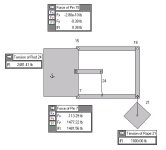
If anyone cares to supply actual data, such as pin-to-pin lengths and weights, I could simulate pin forces. From that I could build a model of the lower link to see where it'll reach it's failure point.

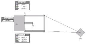
These are with a 1000 lb weight with 31" top and bottom link, 25" rear link. Somewhere about a 50" setback.
 

Attachments

  • Parallel direct.JPG
    Parallel direct.JPG
    23.9 KB · Views: 234
  • Parallel Remote.JPG
    Parallel Remote.JPG
    26.6 KB · Views: 173
   / Conversion Factor for 3PH load capacity #27  
[[ Think more about that //ogram - starting at the tractor body and completed by the implement hookup...If all weight of the load is concentrated at the hookup point it bears straight down on the eyes. Tension and Compression in the links is extremely small and relates to the angle of the links to horizontal. When you extend the load behind the hookup point that same load presses down on the eyes. The torque required of the tractor hydraulics doesnt change but the torque back tipping the tractor does. T&C forces in the opposing links transfer this torque directly into the tractor body.
larry

Since you keep goin' on on // linkages... here's what would happen. The tractor would break something trying to lift a remote load, or tip back. Sure the effort the tractor sees doesn't change but the moment induced by the links do! Their is a limit to the lift, even w/ // four bar links.
So you apparently still dont know what Ive said. You continue to throw argument into the mix while making re statements of virtually identical descriptions I have made and original misstatements of things you falsely attribute to my statements. The limit to the load is the force at the eyes. The limit to how far back that load can be is the back tipping point of the tractor. Nothing will break unless you add front weight to keep the tractor from tipping - - or maybe drive around over bumps while teetering back and forth. Most people would catch that indication and call it a clue.
larry
 
   / Conversion Factor for 3PH load capacity #28  
You cant without an analysis of the lift geometry. Ideally, it is a parallelogram linkage. If it truly were it would lift the same at the balls and any distance behind them. The closeness with which the 3ph setup matches this determines how much loss in lift you get as you go back from the eyes. The match will vary with the placement of pivot points on the tractor and implement and many are selectable on both ends. Trust #s the manufacturer provides is a conservative average. The best you can achieve is 1:1 -- this would be if the implement rose straight w/o pivoting at all wrt the tractor. The worst would be if the implement pivoted the same as the lift arms [or more:eek:] as it rose. Real life will show a variable % loss across tractor brands due to the non ideal geometry achievable....and to a small extent Friction.
larry

No. When you lift something straight up w/o pivoting it torque does not enter in. If you lift a hammer straight up by the end of the handle or by the head you apply exactly the same upward force. The resistance you must apply to keep the heavy extended end from drooping is surely felt by you but doesnt amount to any work. If you have a boom pole to put on your tractor try lifting it from its tip, middle, and lift eyes while installed. The forces you must apply to lift it will be near the same at each place because it is going up w/o much pivot. Intuitively you would think that it would be a cinch to lift way back at the tip... All that leverage. The linkage cancels it for your lift, making you lift the same full weight of the pole and the tractor 3ph no matter where [rearward of the eyes] you lift from. Likewise for the tractor hydraulics, the linkage cancels the intuitive mechanical disadvantage of where on the length of the pole the weight is as the tractor lifts it.
larry
larry

All on the wrong track. Take a look at how a laboratory balance scale works. The weighing platform is controled with a //ogram linkage so that it does not pivot as the balance arm moves. Consequently it does not matter where on the platform the sample to be weighed is placed.
larry

[Yes, these things can be ignored because their resultant at the eyes is given.]....However, ignoring the fundamentals of a //ogram linkage by modeling it as a simple lever brings no understanding of the factors that cause its superior performance. Getting a "close" answer with your shortcut encourages you into thinking you are considering all the correct factors. You are not. The reason your answer comes close is that, in its normal lift and carry usage the linkage does not lend itself to a purely correct // setup so the manufacturer gives 24" numbers for the degraded setup that actually happens in normal use. These #s come out at about 80% of what is available at the eyes. [Not really all that close.:)]

In order to get 100% of what is available at the eyes all 4 arms must form a true //ogram. -- The top link must be the same length as the lift arms. Also, on the implement, the vert dimension from the pins to top link connection must be the same as that vertical dimension at the link connection points on the tractor body. Now all opposite arms will remain // as they move.

All that remains to test this straightforwardly is to get the vertical going segments of the //ogram truly vertical. [In many cases the tractor body lift link pins are well forward of the top link attach point. -- so the tractor rear would have to be elevated to acheive this.] Set up thusly an implement would rise straight and level and would rise exactly as far as the lift eyes. If you have 2K# lift at the eyes you would be able to lift 2k# minus the weight of the boompole at any point on your boompole.
larry

.......OK. Iv explained it pretty well. Yous are wrong. Im sorry that the mechanics of the situation confuses you. Fortunately there are people who understand it in the world so that it can be used on stuff where appropriate. Like scales, weight cancelation mechanisms, vehicle suspensions, tractor seats, tractor 3phs, robotics, camera stabilizing, etc. It is a shame not to have a glimmer of how this system works to control motion and force over distance. If yous did perhaps you could use it. How in the world could a // linkage allow cantilevering to any distance? [Unless you had weightless elements of infinite strength.] To answer a question not asked: The moment is borne by tension and compression of top and lift links and consolidated in the tractor body. There is no energy in this - only a torque, proportional to the distance out the weight is from the tractor body pivots, trying to tip the tractor backward.
larry

[Exactly! No //ogram linkage on the loader.] That is just simple leverage and you seem to be conveniently ignoring that the lift loss is much greater on FEL than 3ph. Im talking physics - not magic. It predates Merlin. Get a glimmer.
larry

Sorry that I was offensive. I really wish that you could say something correct about this so that we could build a fuller understanding. Learning to spell physics may be a good 1st step to using it. Perhaps you should find something you have a question about. To answer one unasked: [[ The compression/tension on opposing elements actually balance one another, pushing down and up equally.]]

The weldup you suggest is totally unrealistic to what is actually happening.
larry

Good!
There are a few points to look at that you have highlighted in you summary:
[[One reason for this is the near impossibility of setting the 3ph up in perfect //ogram form on all implements. Others you brought out well [[here]].]]

Lets talk about it in the perfect sense. [[ Think more about that //ogram - starting at the tractor body and completed by the implement hookup...If all weight of the load is concentrated at the hookup point it bears straight down on the eyes. Tension and Compression in the links is extremely small and relates to the angle of the links to horizontal. When you extend the load behind the hookup point that same load presses down on the eyes. The torque required of the tractor hydraulics doesnt change but the torque back tipping the tractor does. T&C forces in the opposing links transfer this torque directly into the tractor body. The opposing forces balance.
Extended load 3 cases; 1]Movable links Horizontal - take the horizontal T&C forces directly to the tractor mount points. No force on verticle links, 2]Movable links up - take the T&C forces generated by the overhung load. These inputs are purely horizontal but T&C comes into play in the vertical links to preserve the form. As the top link is pulled it tries to move the assembly down due to its angle, but is balanced by compression of the lift link making an equal effort to rise, 3]Movable links down... Youve got the idea.:)]]

[[No, I didnt think that, but I thot that somehow you thot the lifting force needed would increase as overhang increased even if actual assembly weight didnt. Torque consolidated in the earth moorings has to take the the increased strain along with the associated T&C elements of the structure.]]

Thanks for taking a serious look at this.
larry

So you apparently still dont know what Ive said. You continue to throw argument into the mix while making re statements of virtually identical descriptions I have made and original misstatements of things you falsely attribute to my statements. The limit to the load is the force at the eyes. The limit to how far back that load can be is the back tipping point of the tractor. Nothing will break unless you add front weight to keep the tractor from tipping - - or maybe drive around over bumps while teetering back and forth. Most people would catch that indication and call it a clue.
larry
Since the things I have said are being misrepresented I have consolidated them here so their cohesiveness can be seen. [All except post#25 which is interspersed in a quote.]
larry
 
   / Conversion Factor for 3PH load capacity #29  
I honestly don't know the point you're arguing. My only contention with what you said, or didn't say (originally), is you didn't mention anything about the induced moments on the 3PH. Even with a //, the moment exist and will cause a failure if the component forces in the links are allowed to grow too large. I see now (post 13?) where you mention the moments of the 3PH linkage; I missed that @ 3:30 this morning. That was my original point. The lift will be limited by either the forces of the moment or the forces on the lifting links, with a // being a special case which is not realized here. If it were realized, the moment consideration still holds.

After the moment issue, I think we are on the same page.
 
   / Conversion Factor for 3PH load capacity #30  
Here's a thought;
If the perfect parallelogram is worthwhile it might just be worth doing a project.

OK, it seems that Cat 1 lower lift arms are about 32, 33, 34 inches long.
Gadgets like Pats easy change would affect this by a bit, but that could be dealt with later. The top link is significantly shorter than that, but adjustable in a range of maybe 20 to 30 inches.
Well, that could be extended, but it would tilt the implement WAY back, unless the forward attachment point could be moved forwards 12 inches or more.... I hope to come back to this.
I think it would be impractical to shift the implement's attachment point back 12+ inches to accommodate this, that would bastardize an existing standard and even hacking up 1/2 dozen personal implements to a new standard would not be acceptable (to ME).

With a leveled implement the top pin is very close to vertically above the lower pins, I havn't done a precise measurement or consulted the specs, but could probably find that info.
The distance between these should be matched by the height of the top link's attachment point above the lift arm attachment points.
That would get a true parallelogram, opposite sides being of equal length.

Ahh, here's the problem (and it is too late to blame old Fergie for this).
Relocating the top forward corner of said parallelogram to get equal opposite sides puts that corner just about in the center of the rockshaft (on a sample class 1 tractor that I just checked, but it is a typical Class 1 tractor).
"Curse that black tractor" You say ?

I think there is a way around this problem.

Any interest ?
No, I do NOT propose hacking up the rockshaft housing and everything in it.
I propose very little "hacking up", in fact I would expect to adhere to the "easily returnable to factory standard" goal.

Is it worth doing ?
How much work, hassle, trouble, etc would it be worth to have this ?
Would it be worth giving up something for ? some feature or function of the tractor.
Assuming that the feature/function given up would be returned when the perfect parallelogram were removed.
 

Tractor & Equipment Auctions

2021 CATERPILLAR D3 LGP CRAWLER DOZER (A51242)
2021 CATERPILLAR...
2022 Chevrolet Tahoe SUV (A48082)
2022 Chevrolet...
2007 Dodge Nitro 4x4 SUV (A48082)
2007 Dodge Nitro...
Iron Cabinet (A50860)
2000 ADDCO DH1000 Message board (A49461)
2000 ADDCO DH1000...
2025 K1912 UNUSED Metal Livestock Shed (A50860)
2025 K1912 UNUSED...
 
Top