Spyder, you seem to have it all figured out, please enlighten me if I am wrong.
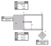
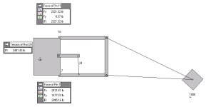
Hitch ratings are devalued, lessening with distance behing attachment. That's a fact in the real word bore out by both theory and what can be realized in practice.
What you seem to be going on about is the fact that no matter how far behind the attachment the load is, the tractor sees the same load. I'll grant you that. One will notice that the weight transfers to the rear tires as the load is extended behind, with the rear gaining the same amount that the front loses. Something about a moment happening there.
The vertical force component (for a given load) bore by the lift arms is a function of the top link angle (to vertical) and distance beyond the lift arm attachment. That's a fact. It works for the case of parallelogram too.
If you keep extending a load out on your boom pole, how far out can it go before there is a failure in the hitch linkage? I'll bet if the top link doesn't fail in tension, the lower link will fail in compression at some point. Or, the front wheels come off the ground. That's a fact.
Where am I wrong so far?
On the cantilevered thing, think of your perfect parallelogram supporting the cantilever. I hope you didn't think that I thought the parralelogram could support anything without the lower link being controlled.
")