$1000 TNT (dual tilt) for BX22

   / $1000 TNT (dual tilt) for BX22
  • Thread Starter
#11  
Modify the cylinders, part 3. The side links get cut.

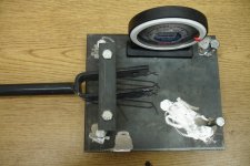
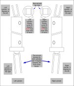
The side links aren't too bad. For the BX22 when using the bailey cylinders, when fully retracted, I just needed enough rod to keep from pinching stuff and give the welder enough room for the bead. I left 1/2 inch of rod total (see picture). There would be 1/4 inch ground off the side of it for the welder, and another 1/4 inch of untouched rod below the weld. You really don't want to go anything less than 1/4 inch between the weld and the seal because the heat from the welding will damage the chrome at least 1/8 inch below the weld which leaves only another 1/8 of good chrome. Not much..

If the OEM links were longer then I would have left more rod, but in this case the cylinders were an inch longer than the OEM links so shorter was better.

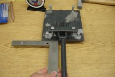
The new side links, once all put together using OEM sized clevis ends, left the total side link length 1 inch longer than OEM. It turned out to not be a big deal. And if I need to get that extra inch back there is enough clearance between the lower links and the top of the side link clevis ends that I can move the pin hole up an inch on the clevis end without any problems. I haven't found the need to do this though.

Next post is how to setup and jig for welding.
 

Attachments

  • Side Link Drawing.jpg
    623 KB · Views: 280
   / $1000 TNT (dual tilt) for BX22
  • Thread Starter
#12  
Time to attach the new ends to the cylinders.. Part 1, top link.

Before describing how things are put back together I need to be sure we are talking the same language so we can stay on the same page.. I will be talking about angles in all sorts of directions using the terms left and right, front and back, and rotation. When I say left or right I'm talking about the direction the end of something will point towards when looking at it as you stand behind the tractor. When I say front or back I'm talking about the direction the end of something will point towards in relation to the tractor in general. And when I say rotate, I will give you a point of reference and give the number of degrees clockwise or counterclockwise something will rotate from that reference.

When I put this together I didn't have a welder and didn't trust welding skills of the friend I knew who did have one (sorry Mark). The welding shop I use charges only $65 per hour with a $25 minimum, which is a SCREAMING deal. Most will charge $90 per hour. But in any case time is money and these days I don't have much of it. So my plan, which worked out well, was to have my friend tack weld the part together then let the pros finish them. This way I didn't waste time jigging each part while the pro's clock ticked along. It ended up costing a bit over the minimum for the entire weld job.

So let's start with an easy one, the top link

Don't have to worry about angles on this one, just rotation or lack there of in my case. The rod end swivel just needs to be straight and centered on the rod. The rod will turn in the cylinder, so it's pretty hard to screw the rotation on that one up.

The non-rod end worked out best when the swivel end aligned with the cylinder ports (See the picture). This way, when using it on the tractor, I can aim the ports up or down by flipping the cylinder over. If the swivel was aligned such that the ports aimed out the side when mounted, flipping the cylinder wouldn't make much difference because the left side of the 3pt hitch looks pretty much like the right side. So if it's in the way on one side, it will probably be in the way on the other side too. But use what you think will work best for you.


The side links come next..
 

Attachments

  • Top Link Align Drawing.jpg
    492.8 KB · Views: 238
   / $1000 TNT (dual tilt) for BX22
  • Thread Starter
#13  
Sorry, didn't mean to leave anybody hanging. The boss has had me working days and evenings, and my landscaping project has been killing my weekend time.. But anyway.

The side links (Rod end).. When I took the side links off the tractor the angles of the ends were pretty intimidating. But thought about it for a bit, it's just a bar with two ends. The ends just happen to angle back to front and side to side at the bottom, and side to side at the top. The rotational difference between the rod and non-rod end didn't matter because you can just give the rod a twist after things are welded if need be.

To figure out the angles I used a flat piece of steal approx 8"x8" ($1 scraps shelf at the welding shop), drilled and tapped each corner, and put bolts with nuts into the holes to make the angle of the plate adjustable. The I drilled and tapped two more holes to make a clamp to secure the side link ends to (see the first two pictures). This jig did a couple things for me, it gave me a consistent way of measuring the angles of the link ends, and it gave me a jig for welding.

How to setup the jig.. Slide the end to be measured/welded under the clamp with the holes of the clevis ends to the sides. Make sure the bar of the side link is square with the end of the plate, and tighten the clamp (third picture). Then, using a level (or eyeball), turn the bolts until the bar of the side link is level and the plate is level from side to side and doesn't wobble, then tighten the lock nuts (fourth picture). The pictures don't show lock nuts, but you want to use something to keep the bolts from turning or be careful not to unintentionally turn the bolts.

The measurements I took from my side links are in the last picture, yours may be different if Kubota changed anything from model to model. But the beauty of this jig is you really don't care what the measurements are since it will allow you to blindly duplicate the OEM angles.

The back to front angle is secured by the screws of the plate (the second picture). To secure the left to right angles, just take a marker and trace the clevis ends on the surface of the plate (the first picture). They are hard to see from the picture, but the non-rod ends are marked there too (Note for the BX22, the non-rod ends didn't have any back to front angles, just left or right).

Now that you have the jig adjusted for the rod ends, use the marks on the top of the plate to line up your new clevis end in the clamp. Square the cylinder with the plate and use shims to make sure the cylinder is level. If the clevis isn't the same height as the cylinder rod, just turn the four corner bolts equally until it is the right height. Then tack the clevis to the rod. That's it. Real easy once you have the jig set.

The non-rod ends are almost as easy, but with them you have to think a bit about port location.

I'll cover the non-rod ends in the next post.. (I promise it won't be as long before the next post this time)
 

Attachments

  • Imported Photos 00029.JPG
    Imported Photos 00029.JPG
    308.6 KB · Views: 276
  • Imported Photos 00030.JPG
    Imported Photos 00030.JPG
    298.6 KB · Views: 243
  • Imported Photos 00034.JPG
    Imported Photos 00034.JPG
    302.6 KB · Views: 216
  • Imported Photos 00035.JPG
    Imported Photos 00035.JPG
    339.4 KB · Views: 235
  • Side Link Align Drawing.jpg
    Side Link Align Drawing.jpg
    63.6 KB · Views: 190
   / $1000 TNT (dual tilt) for BX22 #14  
Wow, nice write up JNJ.

If you want to post pics 'in line', you'll have to host them else where first. Then use the
 
   / $1000 TNT (dual tilt) for BX22 #15  
Excellent!! First class thinking, planning, execution and final product.

You have the type of innovation that keeps America great.
 
   / $1000 TNT (dual tilt) for BX22 #16  
This is outstanding! Adding this to my, "hope to do this some day..." folder.
 
   / $1000 TNT (dual tilt) for BX22
  • Thread Starter
#17  
See.. It wasn't 11 days between posts this time. Only 9. :eek:

Where were we.. Ah yes, the non-rod end of the side links.

With the BX22 I had to consider where to locate the cylinder ports so that the ports and fittings wouldn't bend up the fenders when the hitch is raised. Take a look at the first picture and you'll see where the top port and 90 degree fitting are in relation to the fender.

The trick to making sure you will clear the fender is to consider the worst case scenario. The ball end in the lift arms will allow the clevis to rotate some, so you need to rotate it to towards the fender then figure out the safe angle for the ports in relation to the clevis end. Sounds difficult doesn't it..

Picture two to the rescue! Found it online somewhere. Print it out as multiple pages per sheet and it will print a handful of correctly sized protractors for a 2" cylinder. If they are still not the right size, try to save it as a .jpg and use a photo editor to resize it. Or you can google for a different one.

So how do you use the protractor? Just center it on the bottom of the clevis end such that either 0/180 or 90 is square with the open side and stick it there with a piece of tape (number side up). Raise the lift arm as high as it will go. Now pin the clevis end onto the lift arm and twist it to towards the fender. Eye ball the point where it clears the fender and mark it with a pencil or something. This will be the OUTSIDE of the cylinder port.

Hold the clevis end with protractor onto the non-rod end of the cylinder and line up the mark with the correct side of the port. Now make a mark on the cylinder for the point that is squared with the clevis end. For example, when I taped my protractor to the clevis end, I set the 90 degree to be square with the open side of the clevis. The mark I made on the protractor after holding it up to the fender was on the 65 degree point. So once I lined up my 65 degree mark with the cylinder port, I marked the 90 degree point onto the cylinder. (Please note that when I did it I guesstimated the center point of the port when I marked the protractor. I later determined that the side of the port would have been the more accurate & easy way to go. So where the last picture says the clevis is rotated 25 degrees from the ports, it is 25 degrees from the CENTER of the port. Your number will be different if measuring from the side of the port)

Once you have the mark on the cylinder, draw a line across the middle of the non-rod end of the cylinder using the mark as your reference. When you go to weld the clevis on to the cylinder, this line should run through the middle of the open side of the clevis end.

You can use the same jig as was used for the rod-end work. Do the same setup to figure out the angles, adjust the height, and tack weld the end onto the cylinder. The only difference here is you need to pay attention to where that mark on the cylinder is in relation to the open side of the clevis end.

And BE SURE you have the correct cylinder before you weld. The right cylinder rod end clevis angles to the left and to the front, with a non-rod end angled towards the right. The left cylinder rod end clevis angles to the right and front of the tractor, with a non-rod end angled towards the left. I screwed this up twice.. Yes, twice. :mad: This is why you TACK weld.

Now that you have both ends tacked to the cylinder, carefully pin it to the lift arms and lower arms. I say carefully because it is just tacked and cannot support much load w/o bending or breaking the welds. Now make sure everything fits like it should. If you need to change it, break or grind off the tack welds and adjust as needed.
 

Attachments

  • Imported Photos 00041.JPG
    Imported Photos 00041.JPG
    309.9 KB · Views: 357
  • conventional-protractor.pdf
    38.8 KB · Views: 195
  • Side Link Align Drawing.jpg
    Side Link Align Drawing.jpg
    63.6 KB · Views: 227
   / $1000 TNT (dual tilt) for BX22
  • Thread Starter
#18  
So now you have everything tack welded and you're ready to go all the way with the welds..

Before you, or the pros, hit it with the heat, be sure to extend the rods out (you can use compressed air to actuate the cylinders) as far as possible to keep the seals as far from the heat as you can. Also try to keep the rods/cylinder wrapped in wet towels to help things stay cool (or suggest it to the welder). And be sure to wrap any exposed chrome on the rod with a couple layers of painters tape to protect it from splatter.

If every thing is tacked where you need it and as much prep is done as you can do, if the welder knows what he/she is doing it shouldn't take but 15 or 20 minutes to weld it. Although they may charge you for setup time too (5~10 minutes).

And this is a little late in the game to bring it up, but, don't go overboard with the tack welds. If they are too thick, or gross, they may need to be ground out by the welder after they apply a good penetrating tack. And time is money when your at the welding shop. Also, it never hurts to stop by the welding shop to ask them how they like the surfaces prepped etc. It helps them do a better job, and helps shave some time off the clock.

And when they are all welded up, take the time to give them a good paint job. The paint from the factory is crap, and at least on mine they didn't use primer. I hit every thing with the wire wheel to get rid of the existing paint and slag (wear your particle mask). Then I used a self-etching primer.. You should always use an etching primer on bare metal to get a good bond, it's $15 a can or so but well worth it. So be sure to protect the chrome and be sure to wear a respirator when painting, especially the etching primer because it contains an acid. Then wait a day and hit it with some color.

Looking good? Great!

We'll cover the valve mount etc in the next post.
 
   / $1000 TNT (dual tilt) for BX22 #19  
WOW! Very nice job. Well documented. Thank you for all the info and taking the time to post and take pics. Well done.

YotaBota
 
   / $1000 TNT (dual tilt) for BX22 #20  
Wow, nice job ! I really like that you made both sides tilt, unlike most top & tilt kits. Very thorough explanation also. I look forward to a few action photos in the future. :)
 

Tractor & Equipment Auctions

197711 (A51244)
197711 (A51244)
Miller Trailblazer 250G 4,000 Watt Welder/Generator Set (A51691)
Miller Trailblazer...
2010 Ford Edge SE SUV (A51694)
2010 Ford Edge SE...
2239 (A51244)
2239 (A51244)
378806 (A51572)
378806 (A51572)
2013 Dodge Charger Passenger Car, VIN # 2C3CDXAT6DH646717 (A51572)
2013 Dodge Charger...
 
Top