Can I test the amps from my alternator like this?

   / Can I test the amps from my alternator like this? #101  
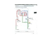
Okay, here is the first diagram and a description of how things work. I have used red to indicate + Battery voltage and Green to indicate - Ground. That way it's easier to follow on a diagram with all black lines.

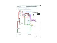
The state of the system is that the key is turned ON, but the engine has not been started.

Positive power (red) flows from the battery to the starter motor and then through a fusible link to the S1 Key Switch. When S1 is placed at ON, the positive power continues down through Fuse #2 to the base of the K1 Safety Relay. Power is felt at the contact of the relay, but it cannot pass through until the relay coil energizes to close the contact. That path is provided by the V1 diode and over to the negative side of the V2 diode. Since V2 is reverse biased, no current flows through it. The positive power contines from the junction under V2 back to the left to the coil of K1 Safety Relay and across the coil to ground (green).

When the coil energizes, it closes the K1 contacts and positive power flows through the contacts (shown as blue for clarity) over to the Voltage regulator via a yellow wire. This signals the voltage regulator to turn ON and be prepared to regulate the power from the dynamo alternator when it begins to have an output. It also sends positive power to the battery discharge light on the instrument panel.

Smitty, what I want you to do is to verify that power is getting to relay K1 and that it is operating as it should. You should see battery voltage at the yellow wire to the VR when the key is turned ON and it should go away when the key is turned OFF. That's the first check I want you to do. If K1 is not operating properly or one of the diodes is bad, we have to fix them before we can proceed. Feel free to ask for any clarification.:)
 

Attachments

  • 4100KeyOnOnly.jpg
    4100KeyOnOnly.jpg
    37.5 KB · Views: 280
   / Can I test the amps from my alternator like this? #102  
Smitty, in another thread you mentioned having a problem finding V1 and V2 diodes. Here is an illustration of the 4100 wiring harnesses. Item #18 shows two rectangles. Those are the diodes and seem to be located near the fuse panel box (item 9).
 

Attachments

  • 4100WireHarnesses.jpg
    4100WireHarnesses.jpg
    55.7 KB · Views: 470
   / Can I test the amps from my alternator like this? #103  
will deffinately have toprint that one out.. my lil 8" netbook screen don't do it justice!

soundguy
 
   / Can I test the amps from my alternator like this?
  • Thread Starter
#104  
Thanks for doing all the color coding. I guess I do have a couple of questions:

1) if either of the diodes or K7 safety relay is bad, I would be getting "no" voltage or current. Right? Because I tested those and I am getting resistance and I am also getting voltage to the K7 relay. I can actually feel the contacts closing when I put my hand on the relay and turn the key on. If either were bad, I would be getting nothing, right?

2) how does the DC voltage get back to the battery? the manual says it travels on the 210red wire which is not color coded on your diagram. It looks like that wire is joined to the white/red wire that goes from the key switch to the starter. Is that right?

3) the only test that I have not done is the amps coming from the alternator. The AC voltage is within specs but I don't know what the amps are. Is that something that could be causing problems?

thanks
 
   / Can I test the amps from my alternator like this? #105  
Thanks for doing all the color coding. I guess I do have a couple of questions:

1) if either of the diodes or K7 safety relay is bad, I would be getting "no" voltage or current. Right? Because I tested those and I am getting resistance and I am also getting voltage to the K7 relay. I can actually feel the contacts closing when I put my hand on the relay and turn the key on. If either were bad, I would be getting nothing, right?

You cannot be sure that K7 is operating properly because you "feel" it energize. The contacts can close, but they can be dirty/burned and not make contact. The only way to tell for sure is to monitor the yellow wire with a voltmeter and observe battery voltage when the key is turned on and no voltage when the key is off.

2) how does the DC voltage get back to the battery? the manual says it travels on the 210red wire which is not color coded on your diagram. It looks like that wire is joined to the white/red wire that goes from the key switch to the starter. Is that right?

I didn't color code the 210red wire because we have not started the engine and the alternator and regulator are not putting out power. Before the engine is started, I want to establish that everything is as it should be. After the engine is started, yes, there should be 14.5 volts DC on the 210red wire.

3) the only test that I have not done is the amps coming from the alternator. The AC voltage is within specs but I don't know what the amps are. Is that something that could be causing problems?

If you are confident that everything is working fine, then do the amps test and tell us what you get, but I have no idea how you ran the tests. Essentially, my idea is to start over and go step-by-step. That's the only way I know how to help you.
 
   / Can I test the amps from my alternator like this? #106  
This is quite the thread!

One thing to point out is a failed device that is drawing current will have hot wires, just like the alternator wire. The only device not subject this test is the main line to the starter solenoid.

If one did a hand temperature check of the wires leaving the fuse box, one ought to be able to put a failed switch to rest.

Also, I didn't see a test of the battery voltage when the tractor wasn't running. This would give an indication of a dead cell(or not).

Finally, measuring the voltage when the tractor wasn't running, with the switch off and on would give an indication of a large parasitic load.

If the tractor starts after setting a while, it is not likely a main line(cable to starter or in starter) short.

If all of those things check out normally, it is the charging system, or is normal.

Chris
 
   / Can I test the amps from my alternator like this?
  • Thread Starter
#107  
hello again jinman (and other nice people)

i have followed the technical manual and run all the tests for the charging system. I will do all the tests again, in order, and I will post my results on monday with voltage numbers.

i put a jumper wire on the K7 safety relay and it checked out fine with either continuity (a beep) or resistance (less than 1) on my meter.

just fyi: the battery shows no sign of a dead cell.
 
   / Can I test the amps from my alternator like this? #108  
Have you been able to locate both the diodes V1 and V2? V2 only comes into play when the relay K7 is deenergized. There is a large reverse voltage spike from the field collapsing around its coil. That reverse spike is conducted to ground through V2. Without V2, the spike will find somewhere to arc and that could be internally in your VR. To check V2, you need to put your meter on the resistance scale and put the leads with red to the positive side of the diode and black to the negative. Take a reading and then reverse the leads. You should get low resistance in one direction and very high resistance in the other direction. Your meter also probably has a diode check circuit, but I'm an old-school guy and normally just use the resistance scale. You can do it either way.

BTW: Dynasim's suggestion for looking for hot wires at the fuse box is good, but since each circuit is fuse protected, I don't see how you could be pulling excessive current there without popping a fuse.
 
   / Can I test the amps from my alternator like this? #109  
Here is a diagram for another test you might do. To get your battery out of the charging circuit and test only your alternator and VR, I suggest cutting or disconnecting the 210red wire and attach it to a 12 volt lamp (35 watts would be good) and ground the other lamp lead. That way the lamp is a load for the regulator output and you let the battery take care of the needs of the tractor during the test. As I've shown in the illustration, with the engine running, the alternator puts out AC to the regulator (pink dashed lines). The regulator puts out the DC to the lamp and you should see it glow brightly. If the voltage is excessive, the lamp will probably burn out or be brighter than normal. You can put your voltmeter on the power coming to the lamp to check what the regulator is putting out. I'd check for DC volts and AC volts.

With this test setup, you can start your tractor and do all the normal stuff with only the battery. This will discharge your battery some, but if it is good, you shouldn't cause any dead battery problems for a very long time and several starts. The benefit you will have is that the battery will provide a reference to the VR as normal through the yellow wire from the Safety Relay.
 

Attachments

  • 4100enginerunwithtest.jpg
    4100enginerunwithtest.jpg
    39.5 KB · Views: 150
   / Can I test the amps from my alternator like this?
  • Thread Starter
#110  
I think the best thing for me to do at this point is follow the technical manual and do all the tests for the charging circuit. I have already done this various times but I don't remember all my numbers to report here today.

I just know that the first 3 tests are: I should read battery voltage at the starter, starter switch and VR...which I do.

then i turn the key to "on" and take more measurements at the alternator and VR. the voltage drops from the previous tests (with key off) because of the solenoids and relays energizing. So, I get a good 1/2volt less at these locations.

I know the biggest problem/question area I have is: the manual says I should have battery voltage at the alternator when the key is "on". I am getting 1 volt less at the alternator than at other areas.

You would think that the problem is the VR, but the VR I have in now was brand new and I was still getting this reading.

any ideas what could be causing that drop?

thanks
 

Tractor & Equipment Auctions

2022 Club Car Tempo Golf Cart (A51694)
2022 Club Car...
UNUSED FUTURE FT-SCW46 STEERABLE COMPACTING WHEEL (A51248)
UNUSED FUTURE...
UNUSED FUTURE 40" HYD TILTING BUCKET (A51248)
UNUSED FUTURE 40"...
2008 CATERPILLAR 304C CR EXCAVATOR (A51406)
2008 CATERPILLAR...
PALLET OF GOLF CART TIRES (A51248)
PALLET OF GOLF...
(INOP) JOHN DEERE 730 CRAWLER TRACTOR (A51247)
(INOP) JOHN DEERE...
 
Top