Deere 4115 Fried Control Module Part M807913

   / Deere 4115 Fried Control Module Part M807913 #1  

hawk7

Bronze Member
Joined
Jan 30, 2006
Messages
76
Location
St. Louis Area
Tractor
4115 Before
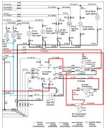
I have a 4115 Deere that has been Stating great and running great. Last time I ran it was 3 weeks a go. Never have had any issues with it starting and it is kept in a insulated finished barn. I went to fire up tractor Monday and the battery was dead. Tractor would only click when trying to start. Don't know why and the key was OFF. Tried to charge and quick charge for 10 minutes and still wont start. Jumped it with the car and all was well. Started pushing snow. Smelled an electrical smell 5 minutes later. Got off tractor and looked around sniffing. Found nothing and thought maybe it was just me since it was 2 out. Tractor died 15 minutes later.Had to jump it again and all was well till i put it in gear and it died. Check seat switch and it was fine. Towed tractor to my barn and started looking around. Wanted to check seat switch wiring at control module with my Fluke. Could smell electrical when I was under the seat. I pulled out the control module and opened it up and the resistors inside where fried. Had moister inside the box. Not sure if this was the issue or if the moisture formed do to the heat inside the box from the fault and then cooling down. Hate to put another one in with out knowing if something caused this??? I charged up the battery and pulled all 3 main power fuses. Hooked meter up in series and check amperage with key off. Put F1 in going to ignition switch and all was well. 0 Amps. Put F2 in feeding regulator/rectifier. All was well 0 Amps. Put F3 in feeding K2 engine pre heater. All was well. 0 Amps. With this said I don't know why my battery was dead. All these test where done with a bad control module hooked up, so not sure if that would have any affect or not. Don't think so looking at the print. Any help would be great. I know I need to check the charging circuit as maybe this ran the battery down the last time I used it. I cant fix the board as it damaged it pretty bad. Any one have one of these sitting on the shelf wanting to sell??
 
   / Deere 4115 Fried Control Module Part M807913
  • Thread Starter
#2  
Forgot to mention this part is also used on a 4100 and 4110 so if anyone has a junk one, let me know and ill buy the control module.
 
   / Deere 4115 Fried Control Module Part M807913
  • Thread Starter
#3  
Why does the fuel solenoid have a pull in coil and a maintain coil? Is the solenoid so hard to pull in they need a direct hook up to the battery through a relay and once its in, the control mod board can keep it held in??
 
   / Deere 4115 Fried Control Module Part M807913
  • Thread Starter
#4  
Update. So far after tracing down all the wires going to the control mod, I ran across 3 wires all hooked together. This was totally wrong per the print. I then looked at a print for a Geared tractor as mine is Hydro stat and found 3 wires hooked together on that print. So basically I must have part of a 4115 Geared wire harness. The print doesn't even show a PTO switch or a rear pto solenoid for the geared tractor so im not sure how you activate and deactivate the pto? Looks like I will be tracing down more wire tonight.
 
   / Deere 4115 Fried Control Module Part M807913 #5  
Why does the fuel solenoid have a pull in coil and a maintain coil? Is the solenoid so hard to pull in they need a direct hook up to the battery through a relay and once its in, the control mod board can keep it held in??

Exactly.

The older 2 wire external linkage solenoids were quite large and took considerable more power to operate.
 
   / Deere 4115 Fried Control Module Part M807913 #6  
Why does the fuel solenoid have a pull in coil and a maintain coil? Is the solenoid so hard to pull in they need a direct hook up to the battery through a relay and once its in, the control mod board can keep it held in??

Yes the pull-in coil uses a lot of current to yank that linkage in. Then think of the linkage being hooked on a mechanical bar that was moved into place to hold it in. That bar does not require any power the hold the linkage. The linkage is simply hooked on it. That bar was moved into place by the holding coil. When power is removed from the holding coil the bar will move back out of the way and the linkage will retract, shutting off the fuel. Below information is from the CTM3 engine manual.

Fuel Shutoff Solenoid
Maximum Pull-in Amperage . . . . . . . . . . . . . . . . . . . . . 50 Amps for 1/2 second
Maximum Hold-In Amperage . . . . . . . . . . . . . . . . . . . . 1 amp continuous
 
   / Deere 4115 Fried Control Module Part M807913
  • Thread Starter
#7  
Good Info, Thanks Everyone. Went and bought the control Module. Went through the Gear print and the Hydro Print. Red Lined everything different between the 2 which isn't a whole lot. My V3 Diode, S8-Seat Down switching side and S7-Rear PTO Switch switching side all have 12V all the time no matter what. This is how they wire the Geared tractors and some how did this one the same. But all the other wiring that is different between the to prints check out fine on my Hydro. Go figure????? It should be this way for a Hydro, V3 Diode only gets 12V when S7-Rear PTO Switch is in gear and not neutral, S7-Rear PTO Switch should only have 12V When K7 PTO Light Relay is closed and it normally is unless S9 PTO switch is on.
 
Last edited:
   / Deere 4115 Fried Control Module Part M807913
  • Thread Starter
#8  
Everything I said above in my opinion didn't cause the A1 Module to fry. Either it fried from,

1. A dead battery and surge the board (Still don't know why and think this could be another issue) Also the board looks like its been getting warn for a while. OR Maybe a shorted batter?

2. Moisture in the A1 Module which has at least 1W resistors in it that heat up and cool down creating condensation build up possibly.

3. The A1 Module was trying to pull in the Y2 Fuel coil the rest of the way creating high amps.

I am leaning towards 3 based on what everything looks like and the tractor was running for 15 minutes before this happened. The resistance on the pull in coil is .6 ohms and the hold in is 22 ohms. This is exactly what a new one meters. So if there is any mechanical issues with it or what its pulling in could of caused this failure. If the plunger doesn't fully enter the coil field, It will create high amperage and since F4 fuse takes 15A to blow, Then it could of been drawing 5 to 10 amps and burned up the board over the 15 minutes.

SO I am going to install an inline fuse for 2A on A1 Module point F. This runs out on wire 657 to 656 and is the 12V+ going to K4 fuel Relay and goes to Y2 Shut Off Hold In Solenoid. THANK YOU JD 755 For that awesome info.

I will also add a inline fuse to A1 Module point J for safety. This is feedback from Y2 Shut Off Pull in Coil just in case something bad happened and back fed into the board.

I'm not to worried about the other smaller relays as they aren't a plunger bases solenoid.

I would upload the prints but they are in PDF format and I cant pull just those 3 pages out of the service CD I have. At least i dont know how with acrobat free reader.

Any thoughts on eventing I types??
 
Last edited:
   / Deere 4115 Fried Control Module Part M807913 #9  
For size comparison, here's an old 2 wire. Weighs about 7#.
 
Last edited:
   / Deere 4115 Fried Control Module Part M807913
  • Thread Starter
#10  
Well I hooked up the new module with 2 fuses like I mentioned above. I also change the 2 wires around like the print shows for the HYDRO as it was hooked up like the GEAR print Tried to start it and it cranks but no gas. So right away I looked at the 2 wires I changed. If I put the rear PTO lever in rear only, Then it is basically wired like the GEAR print and V3 is getting 12V. Presto, The tractor starts. This is all so wrong!!!! I went to Deere parts site to see if they listed 2 different Control Modules. One for Geared and one for Hydro. When you look up 4115, There is no mention of Geared or Hydro so that was no help. Is there a number where you can talk to a Deere specialist?? The dealer is not what I need and they are limited on support. At least in my area. The print I have is from CD1 version 7 Commercial and Utility Vehicle Products. DB1481- FEB 05.

My tractor is a 2003 model.
 
   / Deere 4115 Fried Control Module Part M807913
  • Thread Starter
#12  
Good to know. Not sure why they have over 50 pages in the service CD for a geared one and a different print?
 
   / Deere 4115 Fried Control Module Part M807913 #13  
All those gear (CST) pages are only for the 4110. The hydro (HST) pages are for both the 4110 and 4115. The Deere advertising for those models also show the 4115 is hydro only.
 

Attachments

  • 4115 ad0004.jpg
    4115 ad0004.jpg
    264.4 KB · Views: 441
  • 4115.jpg
    4115.jpg
    426.6 KB · Views: 326
Last edited:
   / Deere 4115 Fried Control Module Part M807913
  • Thread Starter
#14  
Anyone have a print for a 4115 Hydro? I am starting to think Deere has different schematics for this tractor even though it was only made for 3 years.
 
   / Deere 4115 Fried Control Module Part M807913 #15  
Not sure what you are asking. I have the same JD service CD with prints for both hydro and gear that you have.
 
   / Deere 4115 Fried Control Module Part M807913
  • Thread Starter
#16  
JD755 (If you have time, look at your print and see if it matches my typo below. THANKS

If you look at the print for the 4115 Hydro,

You will see that the A1 Control Module POINT A comes out to X16, 412 Red, V3 Diode, X25, S7 Rear PTO Switch, X25 755 Brn/Red, Connection point at S5 Transmission Neural Switch 757 Brn/Red, X14, 758 Brn/Red, K7 PTO Light Relay and SO ON.

Well after tracing down my wires this is how mine is hooked up. POINT A comes out to X16, 412 Red, V3 Diode, 757 Brn/Red, X14, 758 Brn/Red, K7 PTO Light Relay and SO ON. So the S7 Switch isnt even part of the diodes circuit like the print shows.

SO the Diode has power going through it as soon as the key is turned and S9 PTO switch is OFF and K7 PTO Light Relay is OFF.

ALSO S7Rear PTO Switch also goes to 757 Brn/Red, X14, 758 Brn/Red, K7 PTO Light Relay and SO ON.

SO I decided to make it like the print and cut S7 Rear PTO Switch and V3 Diode from 757 Brn/Red and series them like the print shows. Well it wont work this way but the print shows it this way??????????????????? Well it did work if I put the S7 Rear PTO Switch in Rear PTO Only. Thats because in this position the switch is closed like the print shows. I started up the tractor and then put S7 in Rear/Mid PTO position and the tractor died

Is there a different print??
If you look in the section about the A1 Control Module on the CD, it states Point A should have power going to it when the key in in the run position. So that statement doesn't even match up with what the print shows. Further more if you look at the geared print you will see how they tie these 2 point together along with a third point I didn't mention, the seat switch. This is how mine is wired.

One more note is 176 Blk. It runs from A1 Module B to X16 and then down to Y3 Rear PTO Solenoid. This cant be and I checked mine and its not like this but that would be a direct SHORT if S8 Seat pull up switch was made and the other conditions where met.

I think I have a print issue or their is a mis print?????

I hooked it back up the way it was and called my dealer seeing if they can take my serial number and match a print to it.

I am now troubleshooting the charging circuit. K3 coil is open and might of burned up when all the other stuff was happening. I check the alternator and it puts out 50V+ when at 2800 RPM. But with the lights on and tractor running, I get 12.2V so im not charging. I still have to chech V1 and V2 diodes.

Will post when I figure this out. But like I told the kid at Deere that told me to hook stuff back up the way it was, There is a reason why we have prints and for it to be wrong and hook it up the way it was disturbs me!!! I deal with electrical prints all the time and know things can be wrong when there are field changes but this was the diagram for the wiring of the tractor and should be correct.
 
   / Deere 4115 Fried Control Module Part M807913 #17  
I wish I could help you. Having 4115 myself, I can only fix the simple stuff. By sending this TTT (to the top) maybe more knowledgeable people can help you. I depend on this site a lot so I am sure someone will come along.
 
   / Deere 4115 Fried Control Module Part M807913
  • Thread Starter
#18  
Newest update: My K3 Safety Relay has an open coil. It is the same relay for the PTO Light. Here is the sad news. Deere want $87 for one. That is pathetic of them to want this kind of money for a simple relay. Makes me want to call them and complain. I found a number on the Relay CA1-DC12V-N. Found the same relay from Digi-key for $5.41.

Based on what I saw on the print. This should energize when the key is turned which must tell the regulator it OK the operate but if the coil is open the regulator will never charge as K3 is indicating a battery reverse polarity. Is this correct???
 
   / Deere 4115 Fried Control Module Part M807913 #19  
I'll look at it some more, but what I traced so far looks the same. Then I thought I would send you mine. Gear is attached here. Hydro on the next post to keep them separate and in sequence.
 

Attachments

  • Gear1.jpg
    Gear1.jpg
    309 KB · Views: 820
  • Gear2.jpg
    Gear2.jpg
    344.1 KB · Views: 1,124
  • Gear3.jpg
    Gear3.jpg
    313.6 KB · Views: 788
   / Deere 4115 Fried Control Module Part M807913 #20  
Hydro.
 

Attachments

  • Hydro1.jpg
    Hydro1.jpg
    316.2 KB · Views: 405
  • Hydro2.jpg
    Hydro2.jpg
    362.4 KB · Views: 390
  • Hydro3.jpg
    Hydro3.jpg
    327.2 KB · Views: 414

Tractor & Equipment Auctions

GENIE S-60 MANLIFT (A58214)
GENIE S-60 MANLIFT...
Chevrolet 2500 Flat bed (A56438)
Chevrolet 2500...
Adams Load Out Conveyor - Stainless Steel Assembly - Baldor Electric Motor (A56438)
Adams Load Out...
2001 FORD F-350 XL SUPER DUTY FLATBED TRUCK (A60430)
2001 FORD F-350 XL...
1981 LINK BELT HSP 8028 (A58216)
1981 LINK BELT HSP...
1611 (A57192)
1611 (A57192)
 
Top