You could get more angle to suit the attachment if your transfer bar had more holes like mine.
My transfer rod IS I in X 2 in, with three 3/4 in holes.
You could make your own with as many holes as you want.
OR add another cyl with variable adjustments.
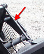
The picture is a PT-425
Bringing this back to the top...
My old 1430 also has the transfer rod with three holes (one on one end and two on the other), and I will be facing the whole rollover/tilt issue with the newly-ordered EA Wicked Compact 50" Grapple. It appears that the back of that grapple, designed for skid steer QA use is only angled/tilted forward about 10 degrees -- considerably less than the PT's approximate 20 degree angle. Based on some experimentation with my pin-on rock bucket, if I use the shortest hole, I get essentially no dump capability, but the bucket will curl upward too far. At about 2 feet off the ground the back of the bucket is about vertical, with the curl/tilt control in the "far down" position. If I use the "longest" hole, the bucket will dump about like my old 425, and curl up slightly for carrying a load in the bucket. So, that appears to be the general length of choice. Using the "shortest" hole may come in handy for using 3-point implements that have been adapted for use, with a vertical QA plate attached. (I've also ordered an EA 60" Land Shark Land Leveler for grading my gravel driveway, so I will soon get to experiment with that.
Land Leveler Land Plane Land Grader Scarifier Shanks for Compact tractors by Land Shark Attachments )
Now onto my real question/issue for discussion. Since I have the lift and tilt rams/cylinders from my old burned 425, I am considering plumbing in one of those to use as my "top link" to make it infinitely adjustable. (At first glance it appears that the lift ram/cylinders would work best due to retracted length being closest to the shortest hole on my existing transfer rod.) I'm thinking of using simple "Tee fittings" so that both the existing and added tilt/curly cylinder would extend and retract simultaneously -- does anyone see any issues with this approach?
My initial concern is getting the added hoses to that second cylinder long enough to handle the full range of motion on the rollover bar's arms, yet keep them as short as possible and protected as well as possible so they do not get "caught/fouled" in the constantly movement of those rollover arms. (My old 1430 has NO hydraulic hoses on the lift arms, and I'm trying to plan out how to route them and protect them as much as possible, welding on tabs/brackets as necessary.)
Thinking this over, I may have to add "stops" on that rollover bar so that I cannot accidentally tilt/curl the attachment up or down too far. I think I may be able to carefully weld on heavy stops on the lift arms and a corresponding tab on the rollover housing -- but I haven't really experimented with that yet... Picture how the stops are welded onto the tractor's male QA plate mechanism to limit how far the individual QA dogs/locks can retract.
Are there other things I should be considering -- or re-thinking? I'm trying to plan all the needed mods to my existing lift arms to convert it to a T-8 QA so I remove the arms and get all the needed welding done at one time. My little 140 amp 110v Hobart can tack on a tab or something, but I can't get sufficient penetration on the 1/2" lift arms to do much there -- only on the crossover "tubes/pipes".
As a couple side notes:
(1) I also considered making a T-8 > skid steer QA adapter like discussed earlier in this thread -- but I decided to forego that approach since it would add 100 lbs or so to the lift arms/QA setup. I'd rather buy an additional QA plate or two, as needed, rather than live with that additional weight. So, I am having EA add the T-8 plate to the new grapple as they build it.
(2) The EA Land Leveler is coming with it's normal Cat 1 3-point. I chose their land plane over buying a King Kutter locally for a bit less money for two primary reasons:
(a) Theirs comes standard with adjustable rippers and provisions for bolting on cutting blades to the back side of the blade mounting bars, and
(b) Just by looking at the pics of it, with its adjustable locations for those cross-bars with the cutting blades, it appears that you could totally unbolt that carriage, and reverse it -- allowing you to set it up to be pushed rather than pulled. (Backing these articulated machines with an attachment on the front in a perfectly straight line is a PITA -- any steering correction swings that implement much more than it effects the steering.) No other land plane that I've seen has that capability. Based on my experience both a box blade and the snow/dirt blade, these PTs as normally configured do not push real well -- they tend to climb up onto the attachment when the going gets tough. But, I think the angle of the QA plate is a factor in this -- because it is tilted forward when the implement is at ground level, forward force tends to push the lift arms UP when pushing hard, preventing you from using float position on the controls. But, if that QA plate was mounted vertical, perpendicular to the ground, this upward force could be reduced somewhat. (Note there is no need to curl a box blade or land plane up and down as much as a bucket.) As a last resort, my oldie 3-pin setup has provisions for a push bar down low, connected just above the front floor of the tub underneath the loader arms. If necessary, I could even adapt or fabricate a similar push bar for the landscape plane. So, I have hopes of being able to push it -- if not successful, I can always pull it.