You are using an out of date browser. It may not display this or other websites correctly.
You should upgrade or use an alternative browser.
You should upgrade or use an alternative browser.
Analysis on log splitter built
- Thread starter polemidis
- Start date
- Views: 3300
More options
Who Replied?
/ Analysis on log splitter built
#11
LD1
Epic Contributor
Agreed. At a minimum your color scale changed. I can't believe that moving the cylinder mount left 2 inches on the beam would have any affect at all on the left edge of the 4 way, and yet it turned from blue to red. Something isn't adding up.
Edit: this was meant to be a reply to s219
It's how FEA tools work.
You gotta look beyond the red to blue color switch. You gotta look at the raw data.
I like to look at the stress.....but he has chosen to display the "displacement" or deflection.
The fact that the 4-way end went from blue to orange means nothing. In fact.....the deflection at that point is exactly the same on both cases.
What happens is the FET tool automatically scales it for you. And you can see in an instant where the weakest link was.
In his first pic....with the anchor block at the end and lit up red.....it shows a displacement of -5.5mm.
In the second, where it shows the 4-way being orange.....it shows a displacement of -0.4 mm.
So even in the first one....that wedge was displacing -0.4mm.....but in the scale.....to encompass the -5.5mm on the anchor block......the wedge area shows up as blue.
So you gotta understand scale when using an FEA tool. Orange and red just show the weakest area of the whole structure.....but that doesn't mean that area is actually weak and/or gonna fail....because you have to look at raw data.
Kinda like if you weigh 200#.....and you step on a 200# scale......you just pegged it into the red. But if you step on a 2000# scale....the needle would hardly move and you would still be in the blue.....your raw weight (raw data) didn't change. Just the scale at which you were measuring with
You are correct. I put the stress numbers on my first post though. Not able to confirm if was something wrong with the mesh creation, this is how it looks now. Be aware that I have not knowledge nor experience on using FEA. I just learn from google here and there.
So if you think that I am using it wrong plz let me know. This current analysis has changed: a) The flange width is 8" instead of 6.5" , and I created pockets so the cylinder mount "ears" and at the 4-way knife can go in and be welded to the full length of the web, plus at the opposite flange.
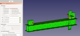
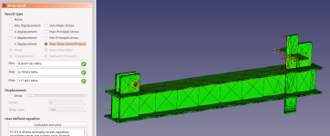
One pic shoes the Von Mises stress, the other the Tresca Stress. I have no idea what these mean though, if anyone can help me PLZ DO! Resources to read, or even a plain explanation, anything that helps me.
The Z displacement is 2mm, which I believe is elastic deformation. Applied force is 35000 Newton


LD1
Epic Contributor
Basically my last post was in attempt to explain how the FEA tool works. As one was questioning why all of the sudden the wedge went from blue to red...(seeming thinking it got weaker)
It did not.
FEA tool is always gonna have green and blue all the way to red and yellow. It don't matter weather you have a 40" tall bridge beam and put a mere 10# load on it. Some point is always gonna be red. Because it automatically scales unless you manually set the scaling.
Hope that makes sense
texasranger556
Platinum Member
I guess my point was you likely can't compare the two pictures absolutely because the color scale is relative to each, as you confirmed in your explanation. Thanks for that.Basically my last post was in attempt to explain how the FEA tool works. As one was questioning why all of the sudden the wedge went from blue to red...(seeming thinking it got weaker)
It did not.
FEA tool is always gonna have green and blue all the way to red and yellow. It don't matter weather you have a 40" tall bridge beam and put a mere 10# load on it. Some point is always gonna be red. Because it automatically scales unless you manually set the scaling.
Hope that makes sense
Matlab does the same thing by default, but you can set color scales manually, change to logrithmic, etc depending what you're trying to show or compare.
Last edited:
LD1
Epic Contributor
I guess my point was you likely can't compare the two pictures absolutely because the color scale is relative to each, as you confirmed in your explanation. Thanks for that.
Matlab does the same thing by default, but you can set color scales manually, change to logrithmic, etc depending what you're trying to show or compare.
Correct. Two pics dont compare because scaling is different.
You said:
I can't believe that moving the cylinder mount left 2 inches on the beam would have any affect at all on the left edge of the 4 way, and yet it turned from blue to red.
I was simply trying to describe WHY it changed from blue to red. Because the reality is the hard data didnt change. And no the cylinder mount didnt have any effect on the 4-way. The change that was made forced the FEA tool to re-scale......thats why it changed from blue to red. But in BOTH pics, the forces and stress on the 4-way are exactly the same
texasranger556
Platinum Member
Understood. I've never used FEA software to know they auto scale every time you plot, which you've cleared up for us. Thanks.Correct. Two pics dont compare because scaling is different.
You said:
I was simply trying to describe WHY it changed from blue to red. Because the reality is the hard data didnt change. And no the cylinder mount didnt have any effect on the 4-way. The change that was made forced the FEA tool to re-scale......thats why it changed from blue to red. But in BOTH pics, the forces and stress on the 4-way are exactly the same
s219
Super Member
- Joined
- Dec 7, 2011
- Messages
- 8,607
- Location
- Virginia USA
- Tractor
- Kubota L3200, Deere X380, Kubota RTV-X
You are correct. I put the stress numbers on my first post though. Not able to confirm if was something wrong with the mesh creation, this is how it looks now.
Yeah, the previous problem was much more than behavior of the color scale -- something was definitely wrong based on the numbers you quoted. But when you are comparing multiple cases, be sure to set the color scale manually so that it's consistent. That way you can make reasonable conclusions about which design is better. This is especially important when dealing with stress concentrations.
DaveOmak
Platinum Member
Thank you.... All of this is WAAAAY over my head... BUT... I do understand the concept of inserting different parts of the splitter into the beam... It all makes sense... Over build everywhere... I planned on boxing in the beam and using it as an oil reservoir also....
