Hydronic heat, I broke it.

   / Hydronic heat, I broke it.
  • Thread Starter
#21  
Thanks for all of the input - the diversity of experience and expertise on this forum always amazes me.

So here's the plan.

It worked before I messed with it. The only change I made was to create that trap with the four 90's


1 - Right now, that trap is actually lower than the main line. I am going to raise it above the main line and replace the two lower 90's with 22 degree sweeps.
This should both shorten the run and get rid of some of the friction.

2 - replace the section of 1/2 inch with 3/4. I dont know why it was installed with 1/2" - but that was 40 years ago.

3 - install a vent at high point/output of the last radiator in the circuit. I don't know why the vent (the #67) exists where it does, but I reckon I will leave it.

These are easy changes that I can knock out quickly.

If they dont work, I think I am in over my head.
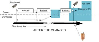
hyd4.jpg
 
   / Hydronic heat, I broke it. #22  
Thanks for all of the input - the diversity of experience and expertise on this forum always amazes me.

So here's the plan.

It worked before I messed with it. The only change I made was to create that trap with the four 90's


1 - Right now, that trap is actually lower than the main line. I am going to raise it above the main line and replace the two lower 90's with 22 degree sweeps.
This should both shorten the run and get rid of some of the friction.

2 - replace the section of 1/2 inch with 3/4. I dont know why it was installed with 1/2" - but that was 40 years ago.

3 - install a vent at high point/output of the last radiator in the circuit. I don't know why the vent (the #67) exists where it does, but I reckon I will leave it.

These are easy changes that I can knock out quickly.

If they dont work, I think I am in over my head.

View attachment 623465

If you keep the "Air traps", whether above or below, without placing vents to clear that trapped air. You are being foolish with your efforts.
Try to understand, the U shape holds an air trap regardless of where it's placed. You must provide a means to purge that air trap. A mono-flow tee won't do it!
 
   / Hydronic heat, I broke it.
  • Thread Starter
#23  
If you keep the "Air traps", whether above or below, without placing vents to clear that trapped air. You are being foolish with your efforts.
Try to understand, the U shape holds an air trap regardless of where it's placed. You must provide a means to purge that air trap. A mono-flow tee won't do it!

Where would you recommend I place a vent?
Being really obtuse here, but would something like this allow air to move to the high point?

hyd sys 5.jpg
 
   / Hydronic heat, I broke it. #24  
nothing is too simple; talk to me like I am 5 years old.

You've been a very, very bad boy!!

I don't understand your diagram in post 13. It shows a "main line" (thick black) that looks like a larger pipe size, below the floor. Then a circuit Tees upward to the radiator(s) in the area that you changed. Then Tees back down. If this drawing is accurate, why would fluid run uphill through the radiators and not simply keep moving along the lower main line instead? Is something missing, or am I not viewing this correctly.

And the air release valve in the low point of the system seems nutty. Accumulated air will accumulate in the high spot, right?
 
   / Hydronic heat, I broke it.
  • Thread Starter
#25  
You've been a very, very bad boy!!

I don't understand your diagram in post 13. It shows a "main line" (thick black) that looks like a larger pipe size, below the floor. Then a circuit Tees upward to the radiator(s) in the area that you changed. Then Tees back down. If this drawing is accurate, why would fluid run uphill through the radiators and not simply keep moving along the lower main line instead? Is something missing, or am I not viewing this correctly.

And the air release valve in the low point of the system seems nutty. Accumulated air will accumulate in the high spot, right?

:laughing::laughing: Yeah, if I interpret your interpretation of my interpretation of the as-built system - you are correct in your head scratching. The system is a one-pipe main, so the circuit tee-s off to a radiator, through the radiator, and back down to the SAME main pipe.

Picture me when we first moved in - laying on my back in the dirt with a flashlight trying to figure it out - why is the radiator "in and out" going to the same pipe?

Also agree about the air valve - I don't know why it has an air valve UNDER the house. I replaced the original manual bleed with a an automatic thingy a couple of years ago.

Anyway, it all worked fine until I added that U shaped section.
 
   / Hydronic heat, I broke it. #26  
Add a shutoff to the main line in parallel with the modded loop? ("full-flow" aka "full-open" type only.)

Use the valve to force bleed the loop, or to throttle main, if/as needed.

What SeaBee said about supply. My system was a PITA whether using house pressure, or 'closed' and relying on expansion tank to control volume. :(

Auto-vents were not reliable, limescale and internal gas releases demanded constant attention, bleeding, & adding.

I'd never use any but distilled water again, but I did swear off hydronics, too.:rolleyes:
 
   / Hydronic heat, I broke it.
  • Thread Starter
#27  
Add a shutoff to the main in parallel with the loop. Force bleed the loop, or throttle it, as needed.

That would be the right way - but a MAJOR effort.
The main is Black Iron; maybe 1-1/2, I would have to cut and thread. Maybe disconnect and use standard lengths, I dunno.

See my Avatar? I don't have a Rube Goldberg avatar for nothing -
 
   / Hydronic heat, I broke it. #28  
Where would you recommend I place a vent?
Being really obtuse here, but would something like this allow air to move to the high point?

View attachment 623476


On the schematic included in my previous post, Numbering the radiators From left to right 1,2,3. Place air bleeds at the high point OUTLET of radiator 2 and another air bleed at the high point INLET of radiator 3.

Think of a piping scheme where you WANTED to trap air. a U is the perfect shape, air will trap on one leg or the other. It really doesn't matter how gradual the elevation transition is, the resistance to flow from air trapping will remain. It's the elevation difference, and the fact that air FLOATS on water.

MONO-FLOW TEEs do NOT provide positive water flow. they work on resistance and differential pressure and can't do anything about resistance or trapped air blockage. They just do not provide sufficient flow. Mono-Flow tees are stupid! You need to provide a way to overcome the deficiencies.

Air bleeds are cheap, isolation / shut off valves for the other branch circuits are another choice to assure full water flow, but that gets involved $$$. A single shut off valve placed in the main line After the return branch from radiator 1 could be used to purge air caught in the U trap by forcing full flow through the problem section. But without effective local high point air bleeds, the trap would accumulate air over time.
 
   / Hydronic heat, I broke it. #29  
Could it be that the recirc pump was never designed to put flow thru the radiators? This could explain many things, including the 1/2 in pipe at the end of the radiator circuit.

Heated water will want to rise. If u have a 3/4 tap off the main line, warm water from that will want to rise. That might be what is creating flow thru the radiators. And why the 1/2 inch is necessary at the other end, so any rise there is less. A 3/4 line there would have equal rise and block flow. This would also explain why your new section killed the system. With or without air, you interrupted the rise/fall that was creating flow???
 
   / Hydronic heat, I broke it.
  • Thread Starter
#30  
I recall years ago, someone commented to me - "How hard can plumbing be? Water always flows downhill right?"
 

Tractor & Equipment Auctions

2002 Ford F-350 Crew Cab Pickup Truck (A50323)
2002 Ford F-350...
199296 (A51406)
199296 (A51406)
2010 Ford Edge SE SUV (A51694)
2010 Ford Edge SE...
2019 Ford F-150 XL (A50120)
2019 Ford F-150 XL...
2012 Ford E-150 Passenger Van (A51692)
2012 Ford E-150...
2004 Toro 74246 Turbo Force 60in Zero Turn Commercial Mower (A50322)
2004 Toro 74246...
 
Top