dodge man
Super Star Member
Yes, a pier in the middle would make it a lot stronger.
That’s the plan.If hardpan is just below the mud, jackhammering many #5 rebars that come up into your abutment will ensure it never sinks in the mud. You can get a 120v electric jackhammer for under $200 if willing to buy a tool.
Regarding pre-tension. Thats more for concrete, its a “pre-load measure” to prevent cracks from opening in the concrete upon tension. Which is obviously not good for concrete structures.
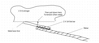
For your steel bridge pretension is OK but not required. As the loading increases, the stringers flex just a little and the cables will tension and stop the flex. I wouldn’t add turnbuckles. Of course you want to take out the cable slack. There are many simple ways. Maybe with a temporary turnbuckle or DIY cable puller arrangement. But do you have a cable crimper?
Rebar welded to flatbar is likely the easiest. Pull tight then weld it down at the end. Clamp it flat and weld some more to hold the tension.

Rebar is terrible when loaded by itself in compression. This is situation if you drive it into the ground to support the abutment.If hardpan is just below the mud, jackhammering many #5 rebars that come up into your abutment will ensure it never sinks in the mud. You can get a 120v electric jackhammer for under $200 if willing to buy a tool.
Regarding pre-tension. Thats more for concrete, its a “pre-load measure” to prevent cracks from opening in the concrete upon tension. Which is obviously not good for concrete structures.
For your steel bridge pretension is OK but not required. As the loading increases, the stringers flex just a little and the cables will tension and stop the flex. I wouldn’t add turnbuckles. Of course you want to take out the cable slack. There are many simple ways. Maybe with a temporary turnbuckle or DIY cable puller arrangement. But do you have a cable crimper?
Rebar welded to flatbar is likely the easiest. Pull tight then weld it down at the end. Clamp it flat and weld some more to hold the tension.
You seem to have some knowledge so I may take this as an opportunity to learn something...
But where are you arriving at your numbers? Or what formulas are you using. This is a little outside my wheelhouse....and lets face it.....this design just isnt common at all in modern design.....
But the closest formulas I am coming up with is the formula for tension in the bottom member of a truss.....which is the bending moment divided by depth.
And in this case.....with 3000# midspan of a 18' beam....(PL)/4 gives me 13,500 bending moment And the total structure with a 6" standoff is 1' total depth. So 13,500 / 1 = 13,500# of tension?
But you are saying a 15x of load would be 45,000# of tension?
Im not trying to dispute your info....as this is kinda a peculiar design and the ONLY time I have ever seen such a design is to strengthen the y-axis on overhead cranes....just trying to learn the correct method of determining tension is this unusual design.
Not to be a total stick in the mud but that doesn't fit my intuition at all, ning. haha.
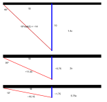
The blue standoff doesn't change dimension at all just because the bridge deflects. it moves with the bridge. I think what actually happens is the top leg of the triangle stretches/elongates.
The way you described it, lessening the angle of your triangle towards zero would give the bridge infinite strength. A clear impossibility.
Basically the same thing as rigging.The blue standoff stretches the tension rod, which is fixed at the other end; that point doesn't move at all.
Push down on the bridge does the same thing to the picture as making the standoff longer.
You got the angles backwards. As the angle gets smaller, the tension transferred to the rod increases to infinity. Bigger angle, smaller multiplier (less tension). Smaller angle, bigger multiplier (more tension).