You are using an out of date browser. It may not display this or other websites correctly.
You should upgrade or use an alternative browser.
You should upgrade or use an alternative browser.
Starting my bridge!!
- Thread starter Doorman63
- Start date
- Views: 52180
More options
Who Replied?
/ Starting my bridge!!
#101
LD1
Epic Contributor
You seem to have some knowledge so I may take this as an opportunity to learn something...I suspect that there will be considerably more than 5000# of tension on the cable - there's considerable mechanical disadvantage in resisting the collapse of an arch (or resisting a flat surface from becoming a negative arch) unless the angles in the framework resisting it is fairly large. This is why the trusses on a bridge are so tall, so that the angles are large.
[caveat - I'm not an engineer, but I understand triangles, that these triangles are barely worth considering triangles for strengthening purposes!]
With a 6" tall triangle under the bridge standing off a tension rod (or cable), and a 9' wide triangle (for an 18' span), because of the really shallow angle formed in that triangle, you'd end up with huge tension on the rod - probably 15x of the downward weight it's supposed to counter.
If you want to counter 5000# using the tension, your 5k turnbuckle would explode.... even 1/2" grade 60 rebar can only be expected to hold 15k tension (gr 60 rebar - 90k psi tension - 1/2" rebar will have ~0.2 sq in). 1" gr 60 rebar would hold about 72k tension, which is what 4800# over the bridge would put on such a system.
With a 12" tall triangle, the tension would multiplier would be about 10x (vs 15x with the 6" triangle) because the angle is larger, and the rod would have accordingly less tension on it.
An 18" triangle gets a 6x multiplier.
The taller the triangle is, the lower the tension multiplier gets; if your bridge was over a canyon and you had a 9' tall triangle so that the cable made a 45* angle to it, holding off deflection would only require about (weight + 40%) tension... but you've got a little creek and you don't want the tension rod/cable to catch stuff that's floating in high water.
But where are you arriving at your numbers? Or what formulas are you using. This is a little outside my wheelhouse....and lets face it.....this design just isnt common at all in modern design.....
But the closest formulas I am coming up with is the formula for tension in the bottom member of a truss.....which is the bending moment divided by depth.
And in this case.....with 3000# midspan of a 18' beam....(PL)/4 gives me 13,500 bending moment And the total structure with a 6" standoff is 1' total depth. So 13,500 / 1 = 13,500# of tension?
But you are saying a 15x of load would be 45,000# of tension?
Im not trying to dispute your info....as this is kinda a peculiar design and the ONLY time I have ever seen such a design is to strengthen the y-axis on overhead cranes....just trying to learn the correct method of determining tension is this unusual design.
Joe1
Platinum Member
Would a used steel trailer truck flatbed not be quicker and easier than "stick built construction"? There must be some used ones for sale where the body is sound. The rolling gear isn't needed, and if in good condition could be sold. It may need redecking. These trailers haul some 50,000 lbs.; are 8' wide and come in lengths of 24 - 40 feet or more Longer than the 20' span would give you plenty of solid material on each side of the creek to be set on solid reinforced ground. With the cost of building materials today, this may be a more economical way to go and would probably be a whole lot quicker and last longer that wood.
It may be worth considering.
It may be worth considering.
LD1
Epic Contributor
He got free/scrap material. Thats something I can appreciate and have done many projects simply because I have the time and means and material....even though "easier" would be to buy something ready to use.Would a used steel trailer truck flatbed not be quicker and easier than "stick built construction"? There must be some used ones for sale where the body is sound. The rolling gear isn't needed, and if in good condition could be sold. It may need redecking. These trailers haul some 50,000 lbs.; are 8' wide and come in lengths of 24 - 40 feet or more Longer than the 20' span would give you plenty of solid material on each side of the creek to be set on solid reinforced ground. With the cost of building materials today, this may be a more economical way to go and would probably be a whole lot quicker and last longer that wood.
It may be worth considering.
And knocking running gear off a trailer is nice in theory....but you have to have a way to handle and position something of that size also
That about sums it up!!He got free/scrap material. Thats something I can appreciate and have done many projects simply because I have the time and means and material....even though "easier" would be to buy something ready to use.
And knocking running gear off a trailer is nice in theory....but you have to have a way to handle and position something of that size also
So far I’ve got $200ish invested
Maybe another $500 in concrete
Another $200 in steel….maybe
A couple nice days working outside
Bringing something “in”…..trailer/connex/etc is gonna require MONEY…….we are currently building another structure on-site. The bridge is something to keep me busy while we wait for the building to be built
Streetcar
Veteran Member
My degree is in civil engineering and I have worked as structural engineer.My degree is in civil engineering and I had structural engineering classes also. I am by no means a structural engineer so take this for what it’s worth.
I never studied, heard of or ever seen a steel structure pretensioned with cables. I’m not saying it won’t work, I just have my doubts. With concrete beams they often pretension or post tension them with cables embedded in the concrete.
I also think I saw someone throwing out the idea of building rails to truss up the main beams with rebar welded up. Once again, I feel that’s not going to do a thing. That’s not what rebar is designed for and I don’t feel the welds would hold. Look at through truss bridges the way the joints are bolted and have gusset’s to strengthen the joint.
I‘ll add I think you’ve got a good bridge, nice build, quality construction, I just think you want to be careful what you drive across it. You’ve got those main rectangular tubes to carry the main load and I’m not sure at this point you can improve on it. Sorry I’m trying not to be to negative.
the pretensioning will put tube in compression and it will work similar as concrete beam
rebar is just round steel bars. The steel does care about its shape it just resist loads applied to it. Rebar has been welded on many of my projects.
gussets just transfer loads between structural members. They are not designed to strengthen joints
My degree is in civil engineering and I have worked as structural engineer.
the pretensioning will put tube in compression and it will work similar as concrete beam
rebar is just round steel bars. The steel does care about its shape it just resist loads applied to it. Rebar has been welded on many of my projects.
gussets just transfer loads between structural members. They are not designed to strengthen joints
Is more always better?
Would 3/4” rebar make my truss better?
The conversations you guys have are fascinating to me.
Of course in the construction world engineers/architects can sometimes be the death of us tradesman……..
I once napkin doodled a drawing for a contractor whose architect didn’t have any structure drawn for some coiling doors.
The engineered drawing took my doodle and made everything BIGGER and had bracing/knife plates/etc in the way of my doors. A bit of chatting with him brought us a happy medium. This interaction doesn’t always happen like this……
dodge man
Super Star Member
yes heavier rebar is going to be stronger.
I assume when you say rebar welded it’s going in concrete? I’ve never seen rebar used anywhere but concrete. I’m not saying it can’t be used in the OP‘s bridge for trusses, maybe long welds on those flat steel tubes would attach the rebar adequately. It seems the rebar would work well in tension but not compression. The last structural analysis class I had was in 1983, so I can’t remember what members in a through truss design are in compression.
I assume when you say rebar welded it’s going in concrete? I’ve never seen rebar used anywhere but concrete. I’m not saying it can’t be used in the OP‘s bridge for trusses, maybe long welds on those flat steel tubes would attach the rebar adequately. It seems the rebar would work well in tension but not compression. The last structural analysis class I had was in 1983, so I can’t remember what members in a through truss design are in compression.
Lineman North Florida
Elite Member
- Joined
- May 12, 2008
- Messages
- 2,772
- Location
- LaCrosse Florida
- Tractor
- Farmtrac 360 DTC with FEL & John Deere 5093E with FEL ,Kubota SVL 75-2
While I am not an engineer and quite proud of that fact, I still say 1 creosote pole on each side of your structure at mid-span would make your bridge strong enough to drive your truck across with an elephant and 2 clydesdale's in the bed with no issues. 
dodge man
Super Star Member
Yes, a pier in the middle would make it a lot stronger.
Sodo
Elite Member
- Joined
- Apr 21, 2012
- Messages
- 3,311
- Location
- Cascade Mtns of WA state
- Tractor
- Kubota B-series & Mini Excavator
If hardpan is just below the mud, jackhammering many #5 rebars that come up into your abutment will ensure it never sinks in the mud. You can get a 120v electric jackhammer for under $200 if willing to buy a tool.
Regarding pre-tension. Thats more for concrete, its a “pre-load measure” to prevent cracks from opening in the concrete upon tension. Which is obviously not good for concrete structures.
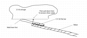
For your steel bridge pretension is OK but not required. As the loading increases, the stringers flex just a little and the cables will tension and stop the flex. I wouldn’t add turnbuckles. Of course you want to take out the cable slack. There are many simple ways. Maybe with a temporary turnbuckle or DIY cable puller arrangement. But do you have a cable crimper?
Rebar welded to flatbar is likely the easiest. Pull tight then weld it down at the end. Clamp it flat and weld some more to hold the tension.
Regarding pre-tension. Thats more for concrete, its a “pre-load measure” to prevent cracks from opening in the concrete upon tension. Which is obviously not good for concrete structures.
For your steel bridge pretension is OK but not required. As the loading increases, the stringers flex just a little and the cables will tension and stop the flex. I wouldn’t add turnbuckles. Of course you want to take out the cable slack. There are many simple ways. Maybe with a temporary turnbuckle or DIY cable puller arrangement. But do you have a cable crimper?
Rebar welded to flatbar is likely the easiest. Pull tight then weld it down at the end. Clamp it flat and weld some more to hold the tension.
Attachments
That’s the plan.If hardpan is just below the mud, jackhammering many #5 rebars that come up into your abutment will ensure it never sinks in the mud. You can get a 120v electric jackhammer for under $200 if willing to buy a tool.
Regarding pre-tension. Thats more for concrete, its a “pre-load measure” to prevent cracks from opening in the concrete upon tension. Which is obviously not good for concrete structures.
For your steel bridge pretension is OK but not required. As the loading increases, the stringers flex just a little and the cables will tension and stop the flex. I wouldn’t add turnbuckles. Of course you want to take out the cable slack. There are many simple ways. Maybe with a temporary turnbuckle or DIY cable puller arrangement. But do you have a cable crimper?
Rebar welded to flatbar is likely the easiest. Pull tight then weld it down at the end. Clamp it flat and weld some more to hold the tension.
Using rebar and skipping the cable.

Posted this pic I scribbled a couple pages ago
Streetcar
Veteran Member
Rebar is terrible when loaded by itself in compression. This is situation if you drive it into the ground to support the abutment.If hardpan is just below the mud, jackhammering many #5 rebars that come up into your abutment will ensure it never sinks in the mud. You can get a 120v electric jackhammer for under $200 if willing to buy a tool.
Regarding pre-tension. Thats more for concrete, its a “pre-load measure” to prevent cracks from opening in the concrete upon tension. Which is obviously not good for concrete structures.
For your steel bridge pretension is OK but not required. As the loading increases, the stringers flex just a little and the cables will tension and stop the flex. I wouldn’t add turnbuckles. Of course you want to take out the cable slack. There are many simple ways. Maybe with a temporary turnbuckle or DIY cable puller arrangement. But do you have a cable crimper?
Rebar welded to flatbar is likely the easiest. Pull tight then weld it down at the end. Clamp it flat and weld some more to hold the tension.
pretensioning works for steel or concrete. It will help in this structure by putting the tube in compression. pretensioning helps because there is less material in the way of getting proper welds and slack in the member is taken up by dead load of the bridge verses the live load of the tractor. Ultimate capacity of bridge will be higher this way.
pier in the middle of the stream can cause debris to build, which could erode abutment in high water
ning
Elite Member
You seem to have some knowledge so I may take this as an opportunity to learn something...
But where are you arriving at your numbers? Or what formulas are you using. This is a little outside my wheelhouse....and lets face it.....this design just isnt common at all in modern design.....
But the closest formulas I am coming up with is the formula for tension in the bottom member of a truss.....which is the bending moment divided by depth.
And in this case.....with 3000# midspan of a 18' beam....(PL)/4 gives me 13,500 bending moment And the total structure with a 6" standoff is 1' total depth. So 13,500 / 1 = 13,500# of tension?
But you are saying a 15x of load would be 45,000# of tension?
Im not trying to dispute your info....as this is kinda a peculiar design and the ONLY time I have ever seen such a design is to strengthen the y-axis on overhead cranes....just trying to learn the correct method of determining tension is this unusual design.
Yesterday when I posted that I just did math assuming the bridge deflected by half of an inch vertically, and considered what that does to the tension rod.
Once again a caveat - I'm not an engineer, don't trust these numbers. They make sense to me right now, but someone will probably properly come along and educate me.
Today while writing this up, I decided to see what the actual math involved is. Note that this is still simplistic because as soon as the bridge deflects at all, the angles change infinitesimally so the math changes. For rough purposes though, we can see what the tension is in the rod instantaneously before any deflection occurs (deflection will occur; the tension rod is there to reduce it; you literally can't eliminate it entirely with metal).
OK? Ok, let's go.
Consider if you have a weight hanging from a rod, vertically. Any vertical deflection will be transmitted directly into that rod, 1:1, no mechanical advantage. Just like if you're winching a load without any snatch block.
What does a snatch block do? It allows you to pull twice as much cable per unit of work done - pulling 2' of cable to move the load 1' - which gives you a 100% mechanical advantage.
Now consider if you have a triangle under the bridge, with a tension rod as the diagonal. The slightest deflection of the center of the bridge will require a lengthening of the tension rod, commensurate with the ratio of the length of the tension rod (the hypotenuse of the triangle) to the height of the triangle, or in math, the cosecant of the angle that the rod forms at the end of the bridge. Bigger angle, smaller ratio, and "better" mechanical (closer to 1:1). Smaller angle, "worse" mechanically (larger penalty).
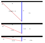
To illustrate consider three bridges with different standoff heights for different angles of their tension rod:
In this picture, the big black parts are the bridges. The blue are the stand-offs for the tension rod, and the reds are the tension rods.
In the first part, the tension rod is at a 45° angle, and any lengthening of the blue standoff (ie, deflection of the bridge in the middle) will require ~1.4x that deflection lengthening of the tension rod - one millimeter deflection is echoed in 1.4mm of tension rod. The deflection is causing a 1.4x stretch in the tension rod; 1000# causing deflection is effectively 1400# tension on that rod.
The second bridge shows a 30° angled tension rod. Because that angle is lesser, every bit of deflection is reflected double in the tension rod; 1mm deflection requires 2mm of rod stretch. 1000# deflection results in 2000# tension in the rod.
The third bridge shows a 10° angled tension rod (with a ~21" tall standoff! 10° isn't much but over 10' it's still almost two feet tall!). The ratio rapidly gets bigger and bigger as the angle lessens - here we have a 5.75x multiplier! A 1000# load is reflected as 5750# tension on the rod!
The smaller the angle gets, the harder any deflection is pulling on that rod, because the slighest deflection causes a much larger lengthening of the rod.
Basically, if you want to stretch a rod, build a really shallow triangle under a bridge and put a weight on the bridge. If you don't have enough weight, make the triangle even thinner so that you have a greater mechanical advantage on that rod. Of course, to strengthen a bridge, we want to reduce the mechanical advantage on the rod, which requires a taller triangle. You can only get so tall, so at some point you need to use a thicker rod to resist the deflection. Also, you have four such rods, so each one only needs to carry on fourth of the tension, though I'd prefer to spec it so that you're way overkill on the rods so that you don't have one break - because if one breaks, its mate on the other side of the triangle will probably pull the standoff over, so suddenly you only have two rods left on the other side of the bridge... and if the bridge load broke one out of four and you now only have two, you're likely to lose the other two as well. Drive fast.
Attachments
ning
Elite Member
Another simple way to look at this:

Obviously in the top picture, the tension on the red cable is the pulling force of the car.
Of the two scenarios on the bottom, which one do you think requires the most tension to hold the car back?
The shallower the angle is between the anchor and the target, the harder it is.
On the top, the cable is at 90°. Bottom right, it's like 50° (workable); bottom left, it's like 20° (much worse).
The shallower that angle, the more tension is required.
A short standoff under the bridge for the tension rods is like the bottom left. Make it as tall as you can get away with.
The standoff needs to be strong enough in compression to handle the load being transmitted to the tension rods, and also it should be reinforced to avoid being pulled apart by the tension rods where they connect.
deezler
Elite Member
- Joined
- Jan 30, 2012
- Messages
- 3,892
- Location
- Southeast MI
- Tractor
- Cub Cadet 7305, Kioti CK3510seh TLB
Not to be a total stick in the mud but that doesn't fit my intuition at all, ning. haha.
The blue standoff doesn't change dimension at all just because the bridge deflects. it moves with the bridge. I think what actually happens is the top leg of the triangle stretches/elongates.
The way you described it, lessening the angle of your triangle towards zero would give the bridge infinite strength. A clear impossibility.
ning
Elite Member
Not to be a total stick in the mud but that doesn't fit my intuition at all, ning. haha.
The blue standoff doesn't change dimension at all just because the bridge deflects. it moves with the bridge. I think what actually happens is the top leg of the triangle stretches/elongates.
The way you described it, lessening the angle of your triangle towards zero would give the bridge infinite strength. A clear impossibility.
The blue standoff stretches the tension rod, which is fixed at the other end; that point doesn't move at all.
Push down on the bridge does the same thing to the picture as making the standoff longer.
You got the angles backwards. As the angle gets smaller, the tension transferred to the rod increases to infinity. Bigger angle, smaller multiplier (less tension). Smaller angle, bigger multiplier (more tension).
LD1
Epic Contributor
Basically the same thing as rigging.The blue standoff stretches the tension rod, which is fixed at the other end; that point doesn't move at all.
Push down on the bridge does the same thing to the picture as making the standoff longer.
You got the angles backwards. As the angle gets smaller, the tension transferred to the rod increases to infinity. Bigger angle, smaller multiplier (less tension). Smaller angle, bigger multiplier (more tension).
Lifting chains and straps get derated when on an angle.
But I think your formula is sound for calculating tension for the example you give....like the car pulling on a cable tethered to anchors.
But I think why your numbers come up so much higher than mine.....is this isn't a freely flexing structure. You cannot discount the ability of the 2x6 itself to resist the load applied. Your formula of whatever weight being applied being a 10x or 15x factor in regards to tension is totally negating the strength of the main beam.
But I like the real world approach the OP is taking for testing deflection and trying ideas to stiffen the bridge.
I think adding a tension member on bottom as well as trussing the top of the beam certainly "can" work well. But it can also fail if done improperly

Here are some similar links:
- Replies
- 19
- Views
- 3K