Help with cylinder placement on grapple

/ Help with cylinder placement on grapple #1  

Stomper

Gold Member
Joined
Jul 1, 2017
Messages
356
Location
Saskatchewan, Canada
Tractor
2017 Kubota L2501
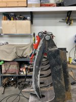
I am looking for help in trying to find the locations to mount a cylinder on my grapple. I have a 12” c to c closed cylinder with a 4” stroke. What is the best/easiest way to figure this out without using a computer.
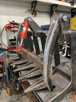
The top cylinder mount and the grapple cross brace are only tack welded and can be moved easily if needed
 

Attachments

  • 93EE5926-EA3B-45E5-859C-DDC9B6A33C83.jpeg
    93EE5926-EA3B-45E5-859C-DDC9B6A33C83.jpeg
    2.2 MB · Views: 391
  • B869C069-F511-4FC6-B7FF-B44825382E15.jpeg
    B869C069-F511-4FC6-B7FF-B44825382E15.jpeg
    2.6 MB · Views: 284
/ Help with cylinder placement on grapple
  • Thread Starter
#2  
I have found this, specifically post #4 but I don’t fully understand what he is saying. If someone could help explain it that would be great
 
/ Help with cylinder placement on grapple #3  
Either you have to do a bunch of math to calculate open and closed positions or take a piece of wood with pin holes to simulate a fully extended and fully retracted cylinder and use those for your gauges.
 
/ Help with cylinder placement on grapple
  • Thread Starter
#4  
Either you have to do a bunch of math to calculate open and closed positions or take a piece of wood with pin holes to simulate a fully extended and fully retracted cylinder and use those for your gauges.
What’s the math way. Is there a formula for this
 
/ Help with cylinder placement on grapple #5  
That cylinder is way too short to give you a half decent opening height and still close all the way.
 
/ Help with cylinder placement on grapple #6  
When I built my grapple or thumb for my loader I calculated the open and closed angles using sine, cosine, tangent formulas based on knowing two of the sides of the triangle.

You should have distance from lid hinge to cylinder mount pivot points. Now it becomes a matter of determining what positioning of the cylinder provides max opening movement and adequate clamping force.

After multiple calculations I got a rough idea on the amount of movement possible and then used two pieces or wood representing extended and retracted cylinder length to very my math was close.

The huge unknown for me was clamp force required.

Probably better ways to calculate but I do not what the formula would be.
 
/ Help with cylinder placement on grapple #7  
Either you have to do a bunch of math to calculate open and closed positions or take a piece of wood with pin holes to simulate a fully extended and fully retracted cylinder and use those for your gauges.
Or you make a drawing to scale, and use a pair of compasses to determin where two radii meet at min and max stroke.
 
/ Help with cylinder placement on grapple
  • Thread Starter
#8  
Or you make a drawing to scale, and use a pair of compasses to determin where two radii meet at min and max stroke.
Can you please elaborate on this please. This sounds like what 3RRL was talking about in the link that I provided
 
/ Help with cylinder placement on grapple #9  
There is the time tested trick of using a couple pieces of PVC that emulate a cylinder...just get similar sized pieces of PVC where one fits in the other and drill some holes...

HD sells 2' sections of PVC...

Good Luck...
 
/ Help with cylinder placement on grapple #10  
What’s the math way. Is there a formula for this
 
/ Help with cylinder placement on grapple #11  
I agree that the cylinder looks to short.

Mocking up with PVC, wood, etc is gonna be easier than all the math in the world. Because some things are easy to overlook in terms of clearances and binding angles.

For example.....with the cylinder base mount offset forward of the lid hinges.....the grapple lid wont ever be able to open much beyond just parallel with the floor. Otherwise the hinges will break over-center and the grapple wont close.....or will try to close backwards.
 
/ Help with cylinder placement on grapple #12  
Get some big pieces of cardboard. Mock up one grapple next to another mock up of the cylinder base mount, full size.
You'll find that 4" stroke isn't going to open enough from closed. That stroke might work on the the "other" side of your pivot but you've already made them and you'd need a cylinder for each side. (similar to the action of a 4/1 bucket) This does provide a better grip on oddly shaped loads.
What you have done looks very nice. 👍
 
/ Help with cylinder placement on grapple #13  
/ Help with cylinder placement on grapple
  • Thread Starter
#14  
Thanks for the help guys. I talked to a buddy at work who is a mechanical engineer in training and he is going to draw something up to see if it will work with the design i have. I am basically trying to copy this design for the grapple lid. 48″ Compact Tractor Root Rake Clam Grapple Attachment Fits Skid Steer Quick Attach – Skid Steer Attachment Depot

He also suggested adding another tine to the middle of the lid and extending it past the back of the top frame and lid pivot points and putting the cylinder on the back of the grapple. Similar to the below design but only one cylinder on the middle tine. Its only a 48" grapple so putting a cylinder on each outside tine on the back is not an option because of the SSQA. I may just go this route. If I did my math correct, with an attachment point of 8" past the pivot point, I should have just over 2000 pounds of clamping force, which should be plenty for its intended purpose.
 
Last edited:
/ Help with cylinder placement on grapple
  • Thread Starter
#15  
From the pictures I have looked at, your cylinder base pivot needs to be behind the lid pivots:

View attachment 790964

And you need a longer stroke cylinder.

Here is one that I have with a unique cylinder mount: Demolition Grapples - Features - Sidney Attachments

View attachment 790972View attachment 790973

View attachment 790974
View attachment 790983
View attachment 790976
I did some figuring using the explanation in the link i posted in my second post and it did placed the mount point behind the top frame
 
/ Help with cylinder placement on grapple #16  
I did some figuring using the explanation in the link i posted in my second post and it did placed the mount point behind the top frame

The rear cylinder pin needs to be higher than the lid pivot pins by at least a few inches. The more distance apart they are the more clamping force you would have. It looks like your cylinder pin and lid pin are almost the same height. The grapple lid pivots really should have been closer to the frame to make it more practical to make the cylinder pin higher. I’m 100 percent sure that the current cylinder is too short to provide a decent opening angle.Here’s a picture of my grapple and demolition bucket for reference. The grapple has a good opening angle but the demolition bucket would be better if it opened more.
IMG_4371.JPG
IMG_4372.JPG
 
/ Help with cylinder placement on grapple #17  
If you are computer savvy a cad package like Fusion 360 can let you mock up the parts and take measurements for the assembly in open and closed positions

A scale cardboard model will work to take physical measurements
 
/ Help with cylinder placement on grapple #18  
I am basically trying to copy this design for the grapple lid.
That doesn’t require any math. When you go to look at one, take a camera and tape measure.
 
/ Help with cylinder placement on grapple #19  
Thanks for the help guys. I talked to a buddy at work who is a mechanical engineer in training and he is going to draw something up to see if it will work with the design i have. I am basically trying to copy this design for the grapple lid. 48″ Compact Tractor Root Rake Clam Grapple Attachment Fits Skid Steer Quick Attach – Skid Steer Attachment Depot

He also suggested adding another tine to the middle of the lid and extending it past the back of the top frame and lid pivot points and putting the cylinder on the back of the grapple. Similar to the below design but only one cylinder on the middle tine. Its only a 48" grapple so putting a cylinder on each outside tine on the back is not an option because of the SSQA. I may just go this route. If I did my math correct, with an attachment point of 8" past the pivot point, I should have just over 2000 pounds of clamping force, which should be plenty for its intended purpose.
Let us know how this works out. I would recommend a computer for a couple reasons - one is to figure out the travel and make quick adjustments if needed. You can figure out whether you have the right piston, etc. The second is to calculate the clamping force. It's pretty easy to do in software.

Let me know if you get what you need from your buddy, if that doesn't work out and you can give me some more dimensions I can draw something up quickly for you.
 
/ Help with cylinder placement on grapple #20  
Agree with others - use CAD: cardboard aided design
 

Marketplace Items

Utility Cart (A59231)
11' CONTAINER (A60432)
2015 Freightliner 122SD T/A Wet Kit Day Cab Truck Tractor (A59230)
2015 Freightliner...
2020 DRAGON ESP 150BBL ALUMINUM (A58214)
2020 DRAGON ESP...
PALLET OF (23) BOXES OF ARMSTRONG TILE FLOORING (A60432)
PALLET OF (23)...
2014 International WorkStar 7300 4x4 Altec AA55E 55ft. Material Handling Bucket Truck (A60460)
2014 International...
 
Top