1610D Volt Reg Wells VR728 no joy

   / 1610D Volt Reg Wells VR728 no joy #41  
evofxdwg - Nice idea, however, I do have a concern. Let me begin by saying that I am in NO way an expert on automotive regulators.

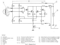
1.) The LM338 is limited to 5 amps continuous, with surge currents up to 12 amps. If you use the headlights frequently, you may have an issue with the regulator not being able to keep the battery charged. From what I remember on the LM338, if the load exceeds 5 amps, the output voltage will drop to keep the heat dissapation of the LM338 within tolerance.

You could add a few darlington pairs, or a few simple 2N3055 series pass transistors, to increase the load capibility, however, by the time you add up the cost and time you may be better off to go back OEM. Of course, this depends on whether or not you treat this as a fun project or science fair experiment /forums/images/graemlins/smile.gif

2.) The filter capacitor (C1) may need to be much larger 1000 mfd. While ripple is not much of a concern to this application, I have no idea what ripple will do the LM338 under full load.

Hope this helps.

Allen
 
   / 1610D Volt Reg Wells VR728 no joy
  • Thread Starter
#42  
thanks for the comments guys

answers for alanp:
1) I could be wrong but the way i read the LM338 datasheet, the current output (not voltage) drops as the temperature goes up (which will happen as current goes up) to limit dissipated power. So yes, it will charge the battery less if it gets hot, but by limiting current output to a safe level. I agree, if i run the headlights a long time, i could discharge the battery. But assuming i can get it to output at least 5 amps continuously using a heat sink: 5 x 14.5 = 72 watts delivered to the battery/load. I havent measured the light draw, but i bet it is not much over that (Does anybody know the wattage of the Yanmar headlamps? maybe 2 total 100W??). And the the power to other items is minimal. So the battery should be able to make up the difference for a while. One reason to stay with the LM338, 5 Amp limit is that I have no idea of max power output of the dynamo - i sure dont want to burn it up! This thing is considerabley smaller than an auto alternator. If i can figure out how to size the dynamo, there are some 10 and 15A circuit examples on National's data sheet using 2 and 3 LM338's.

(2) The 1000uF cap is what National recommended in their suggested "simple" battery charging circuit. Ripple rejection of the LM338 itself is better than 50dB in the ranges i plant to use it (from the datasheet). I dont think there will be a problem with ripple.
 
   / 1610D Volt Reg Wells VR728 no joy #43  
Your single 338 is probably going to be able to handle just about all the dynamo can source.. someone else posted a amp rating.. but it was low.. under 10.

If you could come up with that circuit like you mentioned.. paired.. and have a 10a capacity.. I think you'd be loaded for bear. That or the series pass regulator idea I said.. and another poster (allen? ) mentioned as well. Also.. as anothe rposter mentioned. is this a money saver.. or a project /forums/images/graemlins/wink.gif.. I believe the oem part would be the money saver.. however.. if you are like me.. knowing just how inefficient the oem one is would bug me enough to spend up to twice the $$ to make an elegant fix.. that the next owner won't understand or appreciate!

( To allen: .. don't worry about being up on automotive regulators.. most of them are field regulators anyway.. witht his unit we are stuck with regulating full biased output.. making it a tad harder /forums/images/graemlins/smirk.gif.. but very fun! )

/forums/images/graemlins/wink.gifSoundguy
 
   / 1610D Volt Reg Wells VR728 no joy #44  
The price for my OEM is @ $80. That's a lot of components.

Don
 
   / 1610D Volt Reg Wells VR728 no joy #45  
evofxdwg do you have access to any version of SPICE? That would be an excellent way to simulate the circuit.
 
   / 1610D Volt Reg Wells VR728 no joy #46  
"Bottom line.. as you know.. you have about 15 different options to go from that ac dynamo output to dc battery charge voltage....."

How about this option...

I attached the voltage regulator circuit diagram for the YM186, which should be the same as the YM1610. There are 7 modes of operation:
1. Alternator Stopped
2. Key Switch "Start", Generated Voltage Low
3. Key Switch "Start", Generated Voltage High
4. Key Switch "On", Battery Voltage Low
5. Key Switch "On", Battery Voltage High
6. No Battery, Short Duration
7. No Battery, Long Duration
 

Attachments

  • 566780-Yanmar Limiter.JPG
    566780-Yanmar Limiter.JPG
    43 KB · Views: 1,800
   / 1610D Volt Reg Wells VR728 no joy #47  
That is obviously a simplified diagram, but it is an excellent circuit for the application. Several things are not shown:

1. Something must provide current limiting while charging. Perhaps it is internal to the alternator.

2. Some sort of overvoltage protection is necessary for operation without a battery.

3. There are several places where resistors are required for component leakage compensation and current limiting.
 
   / 1610D Volt Reg Wells VR728 no joy
  • Thread Starter
#48  
Hitek126 and Reb: thanks for posting that. I believe you and Reb are right, that looks like it might be close to actual circuit I have. I now have my broken unit Un-potted. I havent had time to reverse engineer the circuit and i cant identify the TO220 devices nor the power rectifiers. But just a count of the device types matches exept there are way many more resistors and 2 caps on my circuit board:
2 TO220 3 terminal devices (S1, S2?s) - on heat sink
2 hefty metal can 2 terminal devices - (D1, D2?) -on heat sink
4 low power transistors - (Q1-Q4)
5 axial lead package diodes (D3-D6, Z1)
11 carbon resistors (only two on schematic?)
2 axial lead wirewound resistors? or mabye diodes? (in a clear sleeve)
2 ceramic caps

That is an interesting way of regulating voltage/current. I never woulda thought of using SCR's as both rectifiers and current gates in a bridge.

Reb: Im not sure about all those "modes":
Mode 1: If the alternator is stopped (or failed), there is no current/voltage source. The bridge circuit provides isolation between battery and dynamo winding. The only circutry i see detecting this is D3,D4,Q1,Q2, which are there to control the charge lamp. (That's pretty clever too, if Q3, Q4, or Z1 fail "open", the SCRs dont conduct and no current flows. Hence the charge lamp monitors the entire circuit, not just the dynamo output. Of course if Q4 fails "shorted" - the voltage and current go to max and electrons may leak out on the ground - hopefully there is some current limiting not shown as Reb says)

Modes 2,3: Note the regulator doesnt know the difference between "start" and "off" beacuse only one wire (assume key "on") connects to the switch - obviously providing both the charge path and sense batt volltage to the regulator.

Modes 6,7: I dont believe the unit senses if there is a battery out there or not. It simply attempts to put a constant voltage, referenced by zener Z1,out on the yellow wire.

I still think a modern circuit based on LM338 is superior. It has less parts and provides internal current limiting (which i dont see in the old unit schematic). I have measured the 1610D load and determined worst case current is about 4 amps (headlights on high). So an LM338, if it doesnt go into thermal limiting, can provide this with 1 amp to spare for simultaneously charging the battery. The biggest problem with the LM338 in this application is the limited "headroom" voltage (Vout - Vin), which i can overcome if needed by detecting and switching in a series resistor before the LM338 (yeah, a circut that "changes gears" with RPM by detecting high dynamo voltage levels). The dynamo, when measured under several different resistive loads up to 0.5 amp, seems to have a linear voltage to RPM output - independent of current. I need to get a "bigger" load and see what it does at 3 or 4 amps. With these small loads, it puts out 13.3 VAC per 1000 RPM. This can result in nearly 50V peak DC at 2600 RPM out of the bridge rectifier output. And Vout-Vin of around 35 volts.

More when i get around to ordering parts and building it........
 
   / 1610D Volt Reg Wells VR728 no joy #49  
</font><font color="blue" class="small">( I never woulda thought of using SCR's as both rectifiers and current gates in a bridge. )</font>

I like engineering like that. And heck.. I like scr's as well /forums/images/graemlins/grin.gif

</font><font color="blue" class="small">( to the switch - obviously providing both the charge path and sense batt volltage to the regulator.
)</font>

I've seen that used on other charge circuits as well.

</font><font color="blue" class="small">( can provide this with 1 amp to spare for simultaneously charging the battery. The biggest problem with the LM338 in this application is the limited "headroom" voltage (Vout - Vin), which i can overcome if needed by detecting and switching in a series resistor before the LM338 (yeah, a circut that "changes gears" with RPM by detecting high dynamo voltage levels )</font>

I like this too. Most of the time your headlamps won't be on.. and that's plenty of amps to charge. Lots of old tractor electrical systems don't even keep up with the full load of their lamps. Many 6v JD from the 50's with magnetos, and an electric start/lamp kit had a whopping 7 amp rated genny. If you ran the 3 6v 35w lamps with it.. you discharged the battery to the tune of 10a. If you could finad any 12.5w lamp inserts.. you'd be pretty much dead on w/ 3 lamps, and genny at max.. 3/4 amp left over for charge..... or kill the rear lamp and have almost 3a charge...

I don't think your circuit is a bad idea.. you are also working with a limited power plant.

As for 'floating or biasing the ground reference' for the vreg.. I've done that on dip style and some to-220 cases regulators.

Soundguy
 
   / 1610D Volt Reg Wells VR728 no joy #50  
Evofxdwg:

I agree about modes 1, 2 and 3. Mode 1 is a don't care. Modes 2 and 3 are, too because the switch does not connect the alternator output to the regulator.

However, the circuit will know whether there is a battery connected. If the battery voltage is low, the output of the regulator will be clamped to that voltage. The current limit limit of the regulator will be the charging current. If the battery voltage is high, the current out of the regulator will be reduced until the battery voltage plus the output current times the interconnection impedance and battery impedance is equal to the regulator voltage (determined by Z1). The regulator current will be zero when the battery voltage and the battery voltage are equal.

Unless there is something else left out of the schematic diagram, the circuit will do nothing if there is no battery connected. There is no path (except through SCR leakage) for base current of Q5 to turn on the bridge. Therefore (unless the leakage is enough to turn on the Q)the circuit does nothing in modes 6 and 7. If Q5 is turned on in those modes, Q4 will be turned on, shutting off Q5.

Calling these circuits "voltage regulators" is really a misnomer. They are really battery chargers. The output voltage is determined by the battery.
 

Tractor & Equipment Auctions

Kubota BX22 TLB Compact Tractor (RUNS) (A50774)
Kubota BX22 TLB...
2020 EZGO GOLF CART (A50324)
2020 EZGO GOLF...
2018 Ford Fusion Hybrid Sedan (A50324)
2018 Ford Fusion...
2012 Terex RL4 S/A Towable Light Tower (A50322)
2012 Terex RL4 S/A...
Firetruck non runner (A50323)
Firetruck non...
2012 Ford F-150 Crew Cab Pickup Truck (A50323)
2012 Ford F-150...
 
Top