J_J
Super Star Member
- Joined
- Sep 6, 2003
- Messages
- 18,973
- Location
- JACKSONVILLE, FL
- Tractor
- Power-Trac 1445, KUBOTA B-9200HST
JJ, The main circuit relief is an attachment to the HST housing and it is the main relief for the attachment and 3PT circuit. What you may see as a relief valve at the BH valves is what they call a Load Check Valve in one place and an overload relief valve in another (appears to be one assembly performing both functions). There is one in the bucket valve and 2 in the swing valve. They are spring loaded but not field adjustable. The FEL has no relief valve. Attached are some more drawings. Reading the WSM manual it comes clear to me as it seems well worded and complete; I think.
View attachment 364652View attachment 364653View attachment 364654
We've gotten off the track on the OP but now that we started this might as well enlighten a few of our TBNers that eat this stuff up.
Ron
Thanks for posting those hyd schematics.
It make things easier to comprehend.
However on the BH spool, most all valves have load checks on the spools to keep then from moving while shifting, and to prevent back flow into the IN port. They are usually between the work ports or the back side of the valve.
Some spools on some valves will have relief valves to protect that particular function.
If the relief valves are not adjustable, then they will have a set rating for that function.
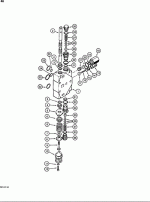
The pic is a spool from my Case D-100 BH. It shows a relief valve for each work port, and a restrictor to slow the speed.
My Inlet section also has a main relief for the BH valve.
All the reliefs uses shims.

