SandburRanch: I missed the point of your observation. Would you explain pls.
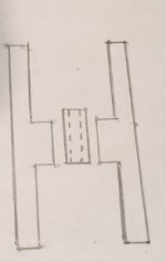
I don't do cad or any of those modern drawings so a crude pencil drawing will have to do, and as anyone can readily see this is not to scale.
The first thing I should mention is, for visual identity, I've exaggerated the amount the sleeve protrudes above the upper bearing outer race Boss ( bearing seat ). The ones I've measured tend to be around 0.010" + -.
If we seat the lower bearing outer race, install the sleeve, then either press or drive the upper bearing in we're doing it in the dark. By this I mean it's difficult to tell
exactly when the inner race of the upper bearing touches the sleeve and that's what is necessary to avoid lateral thrust on the bearing balls and cage. If that upper bearing inner race doesn't just slightly touch the sleeve when we install it the damage will occur when the blade is installed and torqued or when the sheave is torqued as in the video. Reason being is because tightening either of those 2 nuts tends to pull the 2 inner races together.
The flip side. If the inner race touches but the outer race has not been seated, the mechanic or factor assembly person is going to push until it feels solid. If that sleeve spacer protrudes that 0.010" they have just attempted to push all the balls out of both bearings. That's un-due lateral thrust ball bearings aren't designed for and I guarantee they won't last any where their life expectancy.
This is why I rebuild the assemblies myself and modify 1 of the 2 bearings outer race so it's a push fit. This eliminates any guess work. On the LA-135 JD I had at one time the aluminum bearing housings were made so 1 of the bearings was a push fit. Or maybe it was a factory machining mistake but either way it worked out well.