k0ua
Epic Contributor
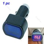
Let me start by saying adding the LED voltmeter was not my original idea. Another member did it to his Kubota, and I stole his idea and even the same product he used, purchased from Amazon.
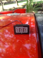
Amazon.com: DROK® 0.40" Waterproof Digital Voltmeter DC 2.5-30V Voltage Tester Red LED Panel Display Car Auto Vehicle 12V 24V Battery Power Monitor; Little DVM Outdoor Gauge for Solar System; Two Wires mode, Self powered, Measuring Lithium Battery, 18
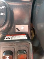
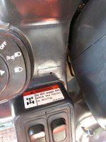
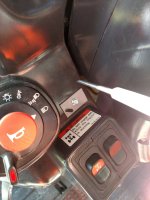
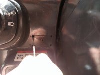
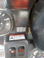
I started by making a plastic template the exact dimensions of the body of the meter (not including the flange or ears) and positioned it on the plastic "dash" of the Kioti and screwed it down. Then taking a sharp scribe I scribed around the template to mark the area needing to be cut out. I drilled 4 small holes in the corners, and inserted a 15tpi scroll saw blade.. this did not work very well at all.
and I quickly got out the dremel tool with a sharp fluted drill bit in it and used that to "mill" sideways thru the plastic. I had some meltback of the plastic in the path of the bit, but going back thru it again solved that pretty quick. Then clean up the edges with a mill bast*** file. Then cut some notches on the left and right edges for the "ears" to have some clearence, but don't go too far as the edge of the meter wont cover the cutout.. Just use common sense.
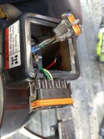
I then punched/pried out the OEM 4wd and emergency flasher switches and their wiring harness, and went in to consult the shop manual. The green wire on on the 4WD switch is key switched 12 volts thru a 15 amp fuse to light the 4wd LED The yellow wire actually pulls a ground thru the 4wd solenoid, so you don't want to mess with that. I chose the little green wire and its corresponding black ground wire.
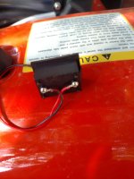
I skinned the green wire just a bit on one side with my pocketknife, and tinned the exposed side of the tiny wire. Then tacked soldered the red wire from the meter on to it. Likewise the black ground wire. I then covered the solder joints with stick-n-seal, because I could not find my scotch liquid electrical tape. RTV would work also. Put everything back together and fire it up. The meter works well, and is much easier to read by eye then the camera would have you believe. I tried to doctor the photo's to enhance them, but suffice to say the meter looks much better in person than the photo.
Full bore off idle is about 14.2 volts. You can see the voltage rise after a startup to the 14.2 running the glow plugs (about 60 amps draw) takes it down to about 10.6 volts. After sitting for a while and before starting it is about 12.5 volts.
Where the meter is located it is pretty well protected and in the shade most of the time. So far I like it.
Well I had about 20 neat pictures. but the upload does not seem to be working
