all in one attachment? is it possible?

   / all in one attachment? is it possible?
  • Thread Starter
#21  
almost there, not much for the servo/motor control, the over all master/slave concept move one, the other one moves.

getting closer, but still not there
https://www.youtube.com/watch?v=V2YWA2xH0oA

vearing off in another direction but getting there
https://www.youtube.com/watch?v=2AJaSAtv0l0#t=44

alright it is a joystick for pc/game but... force feed back control still servo motors.... BUT it is laying down on it's side reflecting out the unit behind the tractor would be seating.
https://www.youtube.com/watch?v=7jkNx1H650c

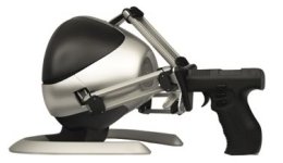
below picture is from...Novint Falcon
BlackFalconSmall2.jpg

gun, swap out handle for a rear blade, or box blade, rotatory deck, post hole digger gear box possibly auger hanging down. what the heck

========
back to hunting for the elusive linear sensors / linear encoders in a style that would fit what i want.

though i may side trac some to see about mini hyd cylinders for the joystick, and tossing away idea of electric over hydraulic pr optional valves. and going pure hyd oil.
 
   / all in one attachment? is it possible?
  • Thread Starter
#22  
LVDT, looks like what i been wanting. basically a short pipe that a metal rod slides through (magnet attached to end of rod) 3 coils of wire inside the short pipe.
LVDTs
How it Works - LVDT
How it Works - LVDT

Inductive Proximity Sensors
Position Sensor and Linear Positional Sensors (adding here before i get about it for a possibilty)

hoping by just running some wires directly out of it (no chips/circuits built onto the sensor), to central computer chip/board were everything connects, sensor itself will be rather cheap to make, remove any seals / wipers. and just let the rod free ride through the short pipe (sensor) and let things take a beating on purpose to some extent. so dust, mud, snow, ice, weeds, rocks/pebbles, etc... can pass some what through or take a few nicks in things, and still keep the sensor going. granted it will be rough, but your not talking heart surgery / space shuttle / air plane, mission critical were it could be life/death situation. by the time a little wear is in the pins/holes that holds everything together. the sensors should still be able to handle things. other words 300 to 700 plus US bucks, vs hopefully 20 to 30 bucks. *rolls eyes in pure amazement in cost of some LVDT)

figure the sensor / rod could be greased down, left out in the rain, etc... and sensor would be perfectly fine.

==================
brings me back to the joystick,
1st option KISS (keep it simply stupid)
add 6 LVDT's to it, and some springs so it returns back to central position every time. and call it quits.

2nd option adding a voice coil to each LVDT in the joystick. to provide force feed back control. and/or the handle could maintain its position from what the rear sensor pickup. other words if ya got a rear blade on, and its angled, twisted, and rotated, so would the joystick handle. if say a pressure relief valve went off for what ever reason and rear blade start to shift some, the rear sensors would pick it up and adjust the joystick handle accordingly. another example if there was a "float option" setup electronically, the handle would move up/down as the rear blade floated up and down on the ground. i would imagine a fail safe feature would be built in, so the handle could only move so fast via force feed back, so ya don't get your hand taken off, or perhaps reduce some of the vibration that the rear sensors would be picking up. kinda bring the seat of paints feeling of vibration and grunt of the tractor back into the operators hand.

voice coil animation
Linear Voice Coil Motors

i am more tempted for 2nd option, (sore neck syndrome) of looking back constantly to keep an eye on things then forward to make sure i don't run into anything.

*rubs chin* i guess for joystick i could go with servo motors (like previous post first video), on second thought, looks a little to easy to snag an overall on, or a sleeve on and rip that thing to pieces.

==============
==============
==============
i think i got basic part concepts worked out except electronics...
need to find another 3D program my autodesk inventor license expired. :/ for a mock up setup, before i start forgetting stuff.
 
   / all in one attachment? is it possible?
  • Thread Starter
#23  
autodesk has a descent monthly pricing option i suppose going on finally. 55 bucks a month for autodesk inventor LT version. use as ya need (no contracts) doing. from other software i have downloaded/tried. 55 bucks a month sounds descent. guess i will tackle what i can, before going with the autodesk thing.

--2nd option above with joystick having "force feed back" is going to get ditched rather quickly. i could quickly see the stupid joystick getting hung up into steering wheel or hitting another lever or button and causing all sort of accidents and incidents. (rear dog tail unit, driving the joystick of were it ends up) *shakes head no*

--to by pass the main joystick control. i do believe 6 buttons (rocker, push/pull, or sliders) will be added.

--wanting ability to lock multi dog tail units (behind tractor) together, either in same direction, or reverse direction.
----same direction locking = move joystick left, and both units behind tractor move left. if ya move joystick right, both dog tail units move right.
----reverse direction locking = move joystick left, first unit moves left, and next dog tail unit moves right. or if ya move joystick up, then first unit goes up, and next unit moves down.
naaaa forget about that. to many extra buttons and options, for actual physical buttons, and would need an actual LCD display or integration to set stuff up through a cell phone or computer.

--i guess a simple "dial" 1-8 i guess. on joystick. to select which dog tail unit behind tractor to control. 1 = nearest dog tail to tractor, 8 = furthest dog tail unit behind tractor.

--i guess i am looking at extreme basic computer chip on each dog tail unit. enough to figure out communication from joy stick and cause raise/lower of voltage, to PWM and reversing.
other words computer chip on each dog tail is rather dumb. with all the high tech stuff at the joystick for advance doings of how things are controlled.

--i guess i need to figure out what i will be using for sensors and solenoid controls and what communication protocol to use. between joystick and chip.
other words... i need to treat the dog tail units behind the tractor as a R/C (remote controlled) car/truck/airplane/helicopter (kids to basically) and then deal with joystick... eewwww....

--wired vs wireless? naaa.. wired. to much of a chance of wireless getting interference and causing major accident. and extra cost to deal with encryption for wireless transmission. wireless option would be better off being placed at main joystick on tractor. vs back on computer chip on each dog tail. so operator seating in tractor could always over ride wireless controls.

===============
i need to get some experience / trail/error testing done i suppose.... i might buy an ardino board, with usb/pc hookup. to get program code figured out. but before that... how the heck do i go about making some mock up version of things on the cheap?

i have made a sch 40 PVC hand pump before. (pumping up a bike tire / basketball or like something low PSI), i could build a few of them to create in idea hyd cylinders.
i suppose i could re-purpose the sprayer pump from the 30 gallon pull behind spray i have.

how the heck do i make the hyd valves though? it would be nice if i could use say 4x4 chunk of lumber. and drill some holes. but the issue with running water and having the lumber swell up.

i wonder how much a 3D printer is. or how much it would cost to have some stuff made.
=================
arghs... how to deal with pressure relief valves, both over pressure and vacuum pressure reliefs.
==================
getting back to were i was.... the LVDT (linear sensors) for joystick and hydraulic cylinders... been kicking myself in the rear. of what i might be able to find at some local hardware store to what i have laying around here. to make a LVDT. more so what can i rob for magnets. or were might i find some magnets that might work locally.

welp time to end here, brainstorming session over.
 
   / all in one attachment? is it possible?
  • Thread Starter
#24  
Jiffy Hitch Sytems, Inc. intresting little gem, never seen one before. could be very useful for this dog tail thing. to help remove / eliminate side to side play within the pins and connectors.
 
   / all in one attachment? is it possible?
  • Thread Starter
#25  
sept 14 Central Illinois Robotics Club i might go join up. due to getting my rear kicked by all the electronics.

LVDT....
http://www.singer-instruments.com/s...ear_Displacement_Sensor_Models_LH_and_LHS.pdf

metal central rod (piston like hydraulic cylinder other words) with a magnet on it. or is a magent itself.
the sensor portion...
going form inside out...
--a wear metal sleeve (rod/sensor constantly grinding on each other, allow for sleeve replacement)
--a thicker hard metal. to handle length and any sort of expansion/contraction.... other words a water pipe freezes, it swells (expands) and then cracks / bursts. i need to keep some thickness of this small short inner pipe, to withstand some expansion/contraction
--coils (3 of them side by side, wrapped around the inner pipe
--outer pipe, again most likely want to keep some thickness of the pipe. to help deal with expansion/contraction.

--ends to connect inner/outer pipe, think of some sort of bushing / reducer fitting. (other words a nut with threads on outside, and thread on inside) and then some sort of wrench spot to tight things with.
below image is from... Electrical IMC Conduit Fittings Zinc Plated Steel Reducing Bushing , Threaded Reducer
pc2228192-electrical_imc_conduit_fittings_zinc_plated_steel_reducing_bushing_threaded_reducer.jpg
*rubs chin* i guess i never have tried, taking 2 pieces of pipe and putting a bushing on each end. this might get a little interesting!

--i am think i should use some sort of "filler" much like submersible water pumps use. to fill in voids and to water tight things for electrical connections. this is to help keep the coils from vibrating and wearing each other down. but also keep snow/water/ice from getting up into stuff. (plowing snow and building up into stuff, to say digging out a hole with water in it) needing a way to make water tight connection up to a point.

--i do believe i am going to want a "pig tail" wires... (no connection directly on sensor) but rather 3 to 5 feet of wire coming out of it. (connected internally to the 3 coils)

--i am not real eager to use expanded metal or a container i should say that is used in a "press machine" or "stamp machine" vs just using regular metal pipe that has a thicker wall of the pipe itself. i realize i will most likely need a slightly higher a/c voltage going into primary coil and maybe more turns of secondary coils to get an accurate measurement... but *shrugs*.

================
calibration... *arghs*

calibration of both joystick LVDT's, and the dog tail unit behind tractor LVDT's, plus each hyd valve will need some calibration. i need the program code, and the function ability of the printed circuit board and computer chip to be able to handle. calibration. along with handling back EMF, if i move a magnet through some coils. i am basically creating a linear generator (creating electricity). and a LVDT could easily create extra electricity. more so of attachment is jittering jattering away as it scrapes across some hard compacted dirt or what not.

the calibration will not be a one time thing.. wear and tear, replacement parts, etc... and calibration will need to be on going. say when ever all the hyd cylinders are fully contracted. and then when they are all fully extended. and operator hitting a "calibration" button. to cause re calibration to happen with new updated info for LVDTs. and say for the individual coils for hyd valves. voltage and/or PWM is slowly raised to extend/contract each cylinder individually till the LVDT's start picking up movement. so computer knows when the actual start happens when a valve begins opening up and/or closes?

==============
all this extra to obtain "generic float function of a 3pt hitch* so simple but so complicated...

looking at various computer chips (audrino, pixaxe, etc...) and getting a bit frustrated, in finding something that has enough I/O (input/outputs) per chip, to handle everything on each DOG tail unit. if i just had to deal with valves for the hydraulic cylinders, that would be easy, but as soon as i add in extra wires for sensors, then i get myself into trouble. both with amount of i/o on the chip, but also i start having to split up the chip's time spent on each task a good amount more, and in that reducing overall precision of sensors. more of an issue, i am not sure some of these already made computer chips can handle what i would toss at it.

============
and off i go getting myself into more trouble! hoping murphy law doesn't flag me down.
Category:Electronic design automation software - Wikipedia, the free encyclopedia
Electronic circuit simulation - Wikipedia, the free encyclopedia
 
   / all in one attachment? is it possible?
  • Thread Starter
#26  
still searching for a chip / circuit board that i might buy off shelf, but not looking good. it is more looking like a custom chip / circuit board, to get all the input/output pins i want in D/C and/or A/C along with correct circuitry in place so as to get away from the back emf, driving circuity to run various coils (in idea motor controllers). and enough processing power to handle "float" and kinda of a "trip" function, along with ability to handle "calibration data" (size of rom/ram/memory just not enough), along with "maintain position" like option (drifting of cylinders) err valves slightly leaking and/or from relief valves kicking on.

i still have option of adding various chips to same circuit board to get what i want. but not to keen on the idea so far.

=========================
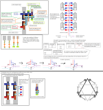
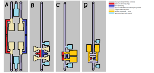
below is older diagram, if brainstorming. trying to figure out how the valves would work....
dog tail valves.png

it took me a while before i realized i could use a "pressure relief valve" and turn what it connects to around. to turn them into "vacuum relief valves" granted it may not be the best idea in the world. but.. what the heck. KISS (keeping it simply stupid)

each hyd cylinder is going to require a bare min of 2 coils (either make it 2 solenoids or 2 D/C motors) to adjust the valves. will most likely chop the 24 coils/valves shown, back down to 12 total coils (2 per each hyd cylinder, then an additional 2 coils per hyd cylinder (one for pressure relief, and one for vacuum relief) to take measurements from. (the pressure and vacuum sensors being for float/trip functionality)

the A,B,C,D,E,F notation of valves. still need to work through, to see if i can combine them and/or redo them to reduce amount of valves.
 
   / all in one attachment? is it possible?
  • Thread Starter
#27  
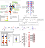
uploading misc scratch drawings... to see what i have.
dog tail valves2.pngdog tail valves3.png

actually looking up hyd schematic symbols to draw things out, vs trying to redraw and figure how to run pipes in a 2D / 3D drawings.
dog tail valves4.png

getting closer, just not there yet.
 
   / all in one attachment? is it possible?
  • Thread Starter
#28  
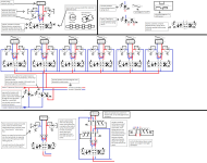
some more chicken scratches.
so far things seem to be panning out better for the bottom set of diagrams, as in it will actual last long term, without any funky hiccups, vs other things i have tried
dog tail valves5.png

with mounting valve directly on hyd cylinder, i would like to think a higher "shock" pressures could be had/handled. (hoping hyd cylinder doesn't implode / explode) due to putting tractor in full high speed reverse and slamming it into something, or vice verses, and chain up to something, with slack in chain, and going for a running start forward.

the individual valve block themselves would most likely need to be some custom job, with a "curve" vs more of a typical "cubed / straight line" valve block, seen on many tractors for extra rear remotes. the curve should take more advantage of the space, and keep the valves from getting in the way and being squished / mangled.

setup should help keep all the hyd hoses and wires located centrally inside of it in idea, to help keep tree branches, weeds, etc.. from sticking up and pulling the guts out of the dog tail.

my only worry is the hoses/wires that go from the 8 way valve / central computer chip, to piston end of the frame work. some extra length will be needed there to be able to stretch out when all hyd cylinders full extend. and when all hyd cylinders fully contracted, that hose length going to want to curl up, or drop down below the dog tail bottom hyd cylinders and give risk to getting snagged by a tree limb or like.

with 2 pressure sensors, 2 coils, 2 lvdt sensors, i am tempted to put a single little chip at each hyd cylinder/valve combo. to reduce number of wires running between each hyd cylinder/valve combo and central computer chip. vs running a dozen or so wires plus 2 hyd hoses from each hyd cylinder/valve combo. though con's vs pro's to each.
 
   / all in one attachment? is it possible?
  • Thread Starter
#29  
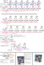
scribbles of figuring out a way to place / mount valves and sensors directly onto the hydraulic cylinder (cylinder portion)
dog tail valves6.png
started to type some code up, and the daunting 96 plus wires... approx 16+ wires per hyd cylinder (valves and sensors) not much worth looking at, more of trying to get an idea of things.
View attachment 388231

i am starting head towards.... "internet of things" type of idea...
==run 2 hyd hoses, and a + and - power cord to each hyd cylinders, and install the valves and sensors, along with a wireless chip, directly on each hyd cylinder. wireless chip being like a chip you might find in a USB/wireless adapter you might buy for a desktop computer.
==then at joystick/s install what amounts to a wireless router (exactly what you might have in your home for internet), to connect to each of the hydraulic cylinders.

i could go with other network protocols along with regular wired network protocols, but with current age of networking for computers, cell phones, etc... and security already built in. (no re-inventing wheel). 16 plus wires coming form each hydraulic cylinder *shakes head no* special end adapters much like "wire harness" adapters/plugs found on nearly every tractor out there. plus cost of wire itself, and connecting the wires to each special wire harness plugs. *shakes head no* i think price would quickly sky rocket. going wireless, would dramatically reduce tracking down a loose or bad wire in 100 plus wires. to only a hand full of wires. and if a hyd cylinder not acting right, being able to narrow it down more directly. getting away from central computer chip that all hyd cylinders use, and if one of the smaller chips go down (on hyd cylinders) more likely cheaper and easier replacement, even for regular folk. a few screws, removing some plugs, and quick easy swap of circuit board/computer chip on each hyd cylinder, or easy to find plug if a valve or sensor plug in.

going with a smaller circuit board and chip at each hyd cylinder, would let a person, order valves/sensors/circuit board, for some DIY project, or addition to some implement, without having to buy a single larger central computer chip, kind of plug&play doing, also gives me a vast more options to choose from, from computer chips already out there on the market. *and the hunt is on!!!*
 
   / all in one attachment? is it possible?
  • Thread Starter
#30  
beyond an actual custom made doing... i do like these little small chip / boards that are stack able / interchangeability. for some of them placed on each hyd cylinder.
Microduino Wikipedia

===========
i been looking at wireless routers, what many folks have in there homes for wifi internet for there tv's, playstations, xboxes, computers, etc.... but more specifically looking at the chips in the wireless routers.
the wireless routers, give of course wifi, but also optional cat5 (rj-45 jack) cable connection if needed and or wanted, security settings for wifi, ability to adjust packet sizes, ability to route data between them if for joystick/controler is only getting a good single to one hyd cylinder wireless router chip, that wireless chip, could send data to the other hyd cylinders much like a wireless access point. there is no extra drivers (software) need per say, for SOC (software on a chip) it is already there within reason.

on some of the wireless chips offerings out there they are "open source" hardware, with dd-wrt, or some other software out there. for extra options, possibly even running a mini web app server, directly on the wireless router chip. i suppose the mini web app server, might be denoted as a mini game app server possibly. the app being, some simple calculations, adjusting the hyd cylinders to a given position. others words, turn this valve on, this valve off. possibly some simple diagnostics, or rather initialization settings. for each hyd cylinder. (setting pressure relief, over all length of hyd cylinder, and piston, along with extension/contraction info. simple notation have not received sensor input from given sensor in x time, send an error to operator (you tore something up), or send warning "pressure relief" has kicked on. i am not confident "float" and/or Trip like function, could be done directly on a wireless chip. i am sure it could, but how fast it could constantly compute the info has me, as an unknown variable.

=============
i have also looked at cell phones of all things, along with battery operated smaller size tablet computers. as being a controller itself, but initially setting up options, max pressure ratings, how much can a hyd cylinder extend/contract, (contracting so far = hitting tire for example), other words basic settings, that only need to be changed once, and/or very rarely (possibly changing settings if hooked up to a different tractor). with some cell phones having tilt / angle / acceleration / 6dof (6 degree of freedom) sensors in them. possibly, going to your cell phone, open up the app, hold finger on a given button on screen and start moving phone, and have the dog tail start moving. or... having simple left,right,up,down, tilt, angle, roll, buttons on the touchscreen, to press. to move the dog tail.

ya cell phone or a tablet computer kinda of out of there... but... say putting on a PHD (post hole digger) onto dog tail. one person on tractor, and another person as a spotter. spotter, turns on cell phone. gives a couple taps, and lines PHD up. and operator on tractor takes over. or like many folks, single person, no one else around, hoping off tractor walking in a few directions to line things up right there with cell phone. and then hoping back up on tractor to run the PHD. to say lifting something into say back of a pickup truck. but everything just not aligning up like wanted. and putting parking break on, hoping off tractor pull on a tug rope to swing things around. and open up cell phone to let things down slowly while off tractor.... ya i realize, some of things folks will do, will be pretty stupid, and i will most likely be one of them. but *shrugs*.

==============
i am still looking at the master/slave joystick / dogtail combo as seen in post 21 video.

but i am also hurting, at looking at trying to figure out a way to have 0-9 buttons, menu, ok/enter, up/down arrows buttons, a LCD screen ((other words... a older school combo printer/fax/scanner/copier machine interface). a touch screen cell phone or smaller size tablet computer. little more cost. but.. a lot more options. via touch screen. plus possible a set of built in instructions / help / faq info. a touch screen cell phone or tablet computer, being able to set up a few different tractors (max pressure settings, extent / contract length of hyd cylinders), and just do a few taps with a finger and select current tractor the dog tail is hooked up to. and go. vs having to re-enter everything each and every time. possibly setting some extra settings for different implements / attachments. trying to do this through a LCD screen and 14 to 20 buttons... would be rather a large hassle. touch screen is more complex...and more likely costly. but... if i could access settings / change settings on initial starting of tractor. and then put cell phone up / tablet up, then grab a hold of joystick while on tractor....and go... go.. goo.. cell phone / tablet. possibly having "warning" sounds, (can you hear when pressure relief valves go off? have a hearing aid? ear muffs on? radio going? inside a cab?, or perhaps even voice commands. how many times have you had hands all tied up, and not an extra to go around. in getting you and tractor out of a jamb... voice commands perhaps.

==============
i am still on the line of wifi, vs wired networking / communication between everything. and only thing that going to solve it... is rough working out the code. so i actually have something i can check against. there is to many small details, that needs to be worked out.


Tractor & Equipment Auctions

1273 (A50490)
1273 (A50490)
2011 Hyundai Sonata Sedan (A50324)
2011 Hyundai...
2011 Ford Explorer Limited AWD SUV (A50324)
2011 Ford Explorer...
Kubota RTV-X900 Utility Cart (A50322)
Kubota RTV-X900...
2008 INTERNATIONAL 4300 M7 SBA 4X2 DUMP TRUCK (A51406)
2008 INTERNATIONAL...
2015 Jeep Compass SUV (A50324)
2015 Jeep Compass...
 
Top