polemidis
Gold Member
I would never guessed, but look what a HUGE difference the Finite Element Analysis results to these models.
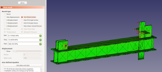
I applied 35000Newtons to the cutting edges, with the cylinder base pin location as the constraint (the red round marks at the right of the pictures)
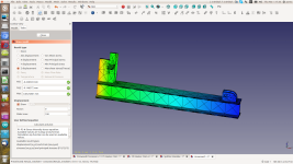
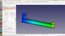
The one at the left shows a distortion to the Z axis of 0.4mm, while the one on the right 5.5mm! In Von Mises streses the left gets 158MPa of pressure, the right one 370MPa. With yield strength of steel of 250MPa that means that the right one will deform in that extreme case.
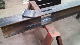
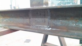
What is the difference? The left one has the has the cylinder mount 2in inside the I-Beam, while the right one has it flush to the end.
I applied 35000Newtons to the cutting edges, with the cylinder base pin location as the constraint (the red round marks at the right of the pictures)


The one at the left shows a distortion to the Z axis of 0.4mm, while the one on the right 5.5mm! In Von Mises streses the left gets 158MPa of pressure, the right one 370MPa. With yield strength of steel of 250MPa that means that the right one will deform in that extreme case.
What is the difference? The left one has the has the cylinder mount 2in inside the I-Beam, while the right one has it flush to the end.
