back hoe hydrolics

   / back hoe hydrolics
  • Thread Starter
#11  
when i can get the camera to work ill put the pics on the internet
i got to fix the blade though
tore the angle plate of when a corner hit a buirredboulder and i didnt notice
im the only kid in my shop class to try anything above soapbox racers
 
   / back hoe hydrolics
  • Thread Starter
#12  
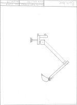
backhoe.jpg
above is the my first back hoe drawings.
 
   / back hoe hydrolics #13  
are you wanting some sugestions on your drawings?
 
   / back hoe hydrolics
  • Thread Starter
#14  
ya that would be great i didnt add hydrolics beacause i dont know how big so i couldnt do them to scale.

ill put pics of the snow plough on a differnt discussion.
 
   / back hoe hydrolics #15  
I would suggest some dimensions so one has an idea of what the length and size of materials your working with.

I would suggest a hing/pivot, that has two points of support, top and bottom,

If you want 180 degree pivot, one more than likely will not be able to have a solid shaft through the middle unless one uses a chain or some type of movable link or rack and pinon system,

you can get about 140 degree pivot with a solid shaft in the pivot,

my guess is your dipper arm has not enough distance above the pivot point to give enough leverage for your desired wants,

If you are intent on the length of dipper and boom (10 and 8 foot), my guess is you will want cylinders in the 3" to 5" diameter and more than likely you need cylinders in the 30" to 50+" in length to make it work,

before one can work out the lengths and the leverage points one will have to start with some potential cylinders in length and there closed and extended dimensions, other wise about all your doing is making a picture,

as the length of the cylinders will be one of the major design points, and one of the things that will be used to make it work and to design your lengths of leverage and so on.

like I suggested, you may be best to some Internet searches and down load some brochures and pictures of backhoes, and get there specs, and see what there using for cylinders and take there picture and blow it up and start to dimension it and then proportion it to your needs, and adjust the cylinder's to match,

and some of your design of your cylinders is what your power unit has for pressure and gallons a min, of hydraulic capacities,

if it is only a 1000 psi system then your cylinders would need to be nearly 3 times the size IN SQUARE INCHES, (area) than a system that is using 3000 psi,

so jsut because a unit has cylinders, that are 5" in diameter 2.5 x 2.5 x 3.14 = 19.625 square inches, X 1000 psi you will have a push of 19,625 pounds, on the return stroke you need to figure the size of the rod and subtract the rod size.

on a 2000 pound system a 3.5 cylinder will nearly be the same, 1.75 x1.75x3.14 = 9.61625 x 2000= 19,232.5 pounds of push,

so before one can figure out your cylinders you will need to know what your skid loader has for auxiliary hydraulic power. and then start to design from there.
 
   / back hoe hydrolics #16  
It may seem like doing the job twice; but making cardboard and/or plywood mock-ups will save you a lot of grief and money when you start fabricating for real on this ambitious project.
 
   / back hoe hydrolics
  • Thread Starter
#17  
i wanted to now if the backhoe in the pic would work
sorry i forgot dimensions it has a 5' arm ,4' dipper ,2' outriigers
 
   / back hoe hydrolics #18  
sorry I messed up and only posted about half of the plan, it is in two URLs

http://www.machinebuilders.net/plans/gallery/Tractor Equipment/Free Backhoe plans-1.pdf

http://www.machinebuilders.net/plans/gallery/Tractor Equipment/Free Backhoe plans-2.pdf

the machine is about the size that your drawing, it has the hydraulics and the basic plans, you basically need the second page it has the dipper and the boom and bucket,

it does not have hydraulic out riggers, but you could probly use the stationary out riggers and jsut lower it to the ground once mounted on the skid steer,

on the frame you would basically jsut want the part from the out rigger tube forward and then a heaver up right for your three point mount,
you would probly have to modify the pivot cylinder to a side mount instead of the rear push/pull it is a possibility two small side cylinders opposite of each other would work better for a three point mount.
take a look at this picture and you may get an idea what I am trying to say,
Backhoe, Build a backhoe, these plans show you how.

some other links you may get some ideas off of.

Micro Hoe <BR>pics 2

CadPlans Corporation - Where you can find designs, tips and order information to build your own backhoes, diggers and MORE!

calculators for a number of different things, hydraulics and sprockets
Baum Hydraulics :: Spec Calculator

~~~~~~~~~~~~~`

I will not say your drawing will not work but as I stated in a early-er post, I think there are some improvements that could be done,
 
   / back hoe hydrolics #19  
It is useful to see a professional use a backhoe, to see what sort of strains they put on the machine, and how they use it. As pointed out, the lower pivot point needs to be quite strong (upper and lower bearing) - it is normal to back the tractor up to your trench line (assuming you are digging a trench, such as for pipe work or similar) and then "fine tune" your alignment ontop of the trench centre line. This involves lifting up the rear of the tractor by pushing the hoe down into the ground (hoe bucket centred on trench centreline) and then (with the tractor rear wheels still in the air) pivot the lower joint until it also lines up over the centreline of the trench. Then when you drag the hoe bucket in towards the tractor it moves along the trenchline (nice, clean & straight trench).

It might sound like this puts a lot of strain on the pivot, but it is a lot less than when you curl the hoe bucket under an unmovable rock and try to lift it out of the ground - still this gives you a good idea of what that lower pivot is going through - lots of strain.

I have an old (heavy) backhoe, the lower pivot is supported above and below, and the supports look like solid 1 inch steel plate. And they have stress fractures in them. It's heavy, clunky, cantankerous and blows a hose occasionally - but lots of fun.

I'm sure you'll enjoy your hoe when built. My only other advise (in case you don't have heaps of money to spend on building the hoe) is to start by scrounging hydraulics - with an eager approach you might find sympathy in a local hydraulics workshop or scrapyard, and having scrounged hydraulics then design your hoe to fit around the bits you have.
 
   / back hoe hydrolics
  • Thread Starter
#20  
thats only 1 of my drawings ive bin looking at lots of backhoes on the internate and have drawn a couple more since
thanks for the ideas
 

Tractor & Equipment Auctions

2002 Blue Bird F131612 Bus (A48081)
2002 Blue Bird...
2020 Kia Rio Sedan (A48082)
2020 Kia Rio Sedan...
2022 Club Car Tempo Golf Cart (A48082)
2022 Club Car...
2018 Generac MLT6SM-STD3 6kW Towable Light Tower (A49461)
2018 Generac...
1969 JOHNSON J25 GOOSENECK TRAILER (A51222)
1969 JOHNSON J25...
2000 Thomas Built Saf-T-Liner MVP-ER Transit Passenger Bus (A48081)
2000 Thomas Built...
 
Top