Bridge Crane designs and ideas...38' span

   / Bridge Crane designs and ideas...38' span
  • Thread Starter
#81  
Ld
Is there an 18 deep beam in your table with similar flange to the small beam. If yes the two beams welded together would be a slightly stronger beam

I wish. The 6x12 has a 4" flange that is 0.280" thick. The lightest 18" beam 6" x 0.425" flange. And that light 18" beam has a smaller moment than teh w12x65 I would be starting with. So that dont work out.

There was this program called "beam boy" that would calculate all sorts of data related to beams and deflection and loading. I can't remember if you could give it custom shapes. You might try looking into that.

For Android smartphones there is an app called epic FEM, but doesn't allow custom shapes far as I know.

Beam boy dont allow custom shapes. (I use beam boy alot). Also tried a couple more beam tools I downloaded, but dont allow custom shapes.

I'm even drawing a blank on the moment calculations by breaking down into individual shapes.
 
   / Bridge Crane designs and ideas...38' span #82  
Ld
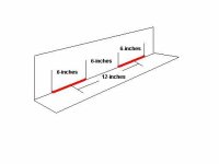
How would the two beam attach to each other? Bolted , continuous weld, intermittent weld
This would affect the strength
I would skip weld it. Most likely go with 6 on 12 weld, and back step it.
 

Attachments

  • 6 on 12.JPG
    6 on 12.JPG
    21.2 KB · Views: 165
   / Bridge Crane designs and ideas...38' span #83  
I'm even drawing a blank on the moment calculations by breaking down into individual shapes.
I'll take a look in my book tonight an see if I can find it.
 
   / Bridge Crane designs and ideas...38' span #84  
Well, if you guys want to make life easier on yourselves, it's just integration -- simple calculus. I don't bother remembering beam formulas (other than simple ones) knowing I can quickly derive them on the fly. My head doesn't have room for all the recipes in the cookbook, so I just remember how to cook from scratch.

Another way you can do complex shapes is to do a full area and then delete the air. So for example, you can compute for an i-beam by doing the full rectangle and then delete the air on each side of the web. For two stacked i-beams, do the full rectangle and then delete the 4 sections of air.

Take advantage of symmetry and just do half the beam (split vertically) and then double the answer.

Parallel axis theorem (google it) can be used to shift moment of inertia from one axis to another. So you can compute about the central axis of the simple shape parts and then transfer to the central axis of the complex shape to add in to the total.

For tallish i-beams where the flange spacing is much greater than the flange width, I bet two stacked beams (assumed to be joined perfectly) will only be fractionally better than a single i-beam of the same total height and web/flange thicknesses. Reason being is that the two joined flanges in the middle are too close to the central axis to have much of an area moment of inertia about that axis. The best way to get area moment of inertia is to have the area far from the central axis. Stuff close in doesn't contribute as much.
 
Last edited:
   / Bridge Crane designs and ideas...38' span #85  
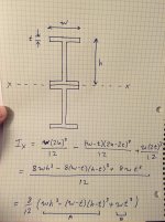
OK, here's an equation that will work for stacked w-beams of uniform web/flange thickness. Can be modified to an i-beam with a little work, or to accommodate different web/flange thickness.

To get this I did the full rectangle, minus the air if the middle flanges were ignored, and then added back in the middle flanges. That allows all moment calculations to refer to a single central axis and lets us do a comparison at the end.

In the final answer, terms "A" would be for a full w-beam of the same total height. The "B" term is the added area moment from the two flanges in the middle, so it gives the contribution of stacking the beams.

eqns.jpg
 
   / Bridge Crane designs and ideas...38' span #86  
So as an example, with h=10", w=3", and t=0.25", the stacked beams give Ix=300.8 in^4. A single beam of the same total height as the stack (so same but no flanges in the middle) has Ix=300.7 in^4. Essentially no real difference.

Based on this, I think that for tallish i-beams or w-beams where the height is 3X the width or better, you may as well just assume that two stacked/joined beams are more or less the same in bending as a single beam of the same height as the stack. That ought to really simplify your calculations.

Again, this assumes the stacked beams are joined perfectly, or in such a way that the joint isn't an issue. You should be able to calculate what type of bolting or welding is required to meet that assumption. Along the central axis of the beam, all the loads are shear loads; there is no tension/compression.
 
   / Bridge Crane designs and ideas...38' span
  • Thread Starter
#87  
Parallel axis theorem.....just the missing piece I was looking for.

Found this....nice video https://www.youtube.com/watch?v=WDdkdC1sFQQ

Working out the numbers for the following....

W12x65 beam
Wf = 12.000
Tf = .605
Tw = .390
Height = 12.1

I come up with Ix = 519 Pretty close. Beam is actually listed at 533 due to the radius I didnt account for. But proved to myself the formula works.

Adding a W6x12 beam underneath...
Wf = 4.00"
Tf = 0.280"
Tw = 0.230"
Height = 6.03"
Ix all by itself... 22.1

Stacking them I get Ix = 759. And in reality probably closer to 800 since I didnt account for the radius where web meets flange.

Dont really gain anything in the way of lifting capacity though.:thumbdown: If I use Bending stress as the ultimate limiting factor. Keeping it 5:1 for safety limits max stress to 7200psi. Adding height to the beam dont do any favors in that department since the beam height (or rather 1/2 the beam height c) is part of that equation.

But what it does do is decrease deflection by about 50%.

Results...single W12x65 beam, 38' span, 5k load in the middle....~6650psi stress, 0.634" deflection
Stacked beams same load and span.........................................~6800psi stress, 0.434" deflection
 
   / Bridge Crane designs and ideas...38' span #88  
How much strength could you add to those beams by adding a top truss?
 
   / Bridge Crane designs and ideas...38' span
  • Thread Starter
#89  
How much strength could you add to those beams by adding a top truss?

I would guess not much. Since the top is in compression and not tension. IF it was a cantilever design, (kinda like a cherry picker) where the top is in tension, then it would be significant. And adding more "light" material making the beam taller seems to have an adverse effect on the stress. While it makes a stiffer beam, it dont really help in the stress department.

I like all this learning and learning new formulas and how to apply them. (thanks S219)

Now on to my next question....and this may be getting into the realm of needing software but I dont know....

The weakest part of the beam is right in the middle. Looking at alot of multi-ton industrial cranes, (and even steel buildings) the "members" get smaller toward the edges. Cause the strength is needed in the middle.

So consider this design and see if anyone has any way to calculate it out.....

Alot of the beams are going to require cutting/splicing (used market for ya).

So what about say.....A w12x65 beam 38' long, but another beam ON TOP, but perhaps not full lenght. I have an assortment of beams on the rack now that could be welded to the top centered up (and likely bridging over whatever splice I need to make)

I have some W8x28 maybe 15' long, Some S10x25.4 about 12' long, some W4x13 about 15' long, as well as some 4x6 and 6x6 1/4 wall box tube, and a C12x20.7 channel about 10' long.

I could use any of these to cap the beam in the middle centered up....but how to calculate that?
 
   / Bridge Crane designs and ideas...38' span #90  
Ld1
Differing sections can be used. You just calculate the beam loads and strengths in the various composite sections you have made.
In most cases welding is easier to join beams verses bolting.
Your calculation for moment of inertia is lower than beam value, Because the beam flanges are slightly tapered. They are thicker near the web
Additional information. Roadways use bolted connection in many cases because of repetitive loads from vehicle, millions of trucks can cause problems with welded connections. Shop crane will not have this issue.

Good luck
 
Last edited:

Tractor & Equipment Auctions

Miller Bobcat 225G AC/DC Welder Generator Set (A49461)
Miller Bobcat 225G...
2013 Ford F-150 Ext. Cab Pickup Truck (A50323)
2013 Ford F-150...
2005 INTERNATIONAL 4300 CARGO TRUCK (INOPERABLE) (A50854)
2005 INTERNATIONAL...
2025 Swict 84in Bucket Skid Steer Attachment (A50322)
2025 Swict 84in...
1981 LINK BELT HSP 8028 (A50854)
1981 LINK BELT HSP...
2019 FORD F-150 XL SINGLE CAB TRUCK (A51406)
2019 FORD F-150 XL...
 
Top