Backhoe Building a thumb for a model 48 Backhoe

   / Building a thumb for a model 48 Backhoe
  • Thread Starter
#11  
Thanks guys for all of your input:
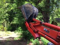
On the greasing of the thumb pivot - I have considered how to supply grease. I see two options: the first is to put zerks into the pivot bosses. The other is to use shallow grease channels in the pivot pin with a zerk on each end of the pin. As I mentioned elsewhere, I had to replace the dipper pin because it was rusted tight in the boom. When I got the new pin, I put it in the lathe and drilled a 3/16" hole from one end all the way into the center and then drilled another small intersecting hole so grease can exit the pin in the center of the boom. Then I milled two shallow channels from the intersecting hole so the grease can pass back outward about 1/3 of the way back out. This way, grease is well distributed over the span of the pivot in the boom. I'm thinking that for this bucket/thumb pin, I'd put in a zerk on each end of the longer pin and drill/mill the channels so grease can be injected into the dipper and then outward to the thumb.

On the stiff stabilizer control: I agree that the stabilizer control levers are stubby and stiff. I would much prefer a separate independent control for the thumb, especially one that is up near the other two controls. I guess it will depend upon cost and how much it is to install. I'm very curious about the splitter twist update!
 
   / Building a thumb for a model 48 Backhoe #12  
There are about half a dozen detailed threads on adding hydraulic thumbs that would be worth looking up for info on valve options, reliefs, modifying pins, thumb configuration, etc. I would not favor milling a grease slot on the surface of the pin because that would increase the likelihood of the kind of failure dfk has mentioned. Flush face fittings on the thumb bosses are easy and safe.
 
   / Building a thumb for a model 48 Backhoe
  • Thread Starter
#13  
There are about half a dozen detailed threads on adding hydraulic thumbs that would be worth looking up for info on valve options, reliefs, modifying pins, thumb configuration, etc. I would not favor milling a grease slot on the surface of the pin because that would increase the likelihood of the kind of failure dfk has mentioned. Flush face fittings on the thumb bosses are easy and safe.

Downsizing: I feel a bit foolish for not thinking of this before. I searched the top level forum for "thumb" and found a treasure trove of threads with photos of thumbs, mostly fixed mechanical. Lots of ideas there to help with working out the design.
 
   / Building a thumb for a model 48 Backhoe
  • Thread Starter
#15  
This weekend I spent some time building a wood model of a thumb. This is just to work out the general geometry. I know that I need to add some support for the pin where it ties into my wood hydraulic cylinder. IMG_2551.JPG

I was pretty happy with this until a friend of mine sent me a photo of his thumb. His thumb tucks in very nicely around the hydraulic cylinder and shields it from damage while digging. Now I'm going to have to modify my design to incorporate this type of configuration.IMG_2055.JPG
 
   / Building a thumb for a model 48 Backhoe #16  
Building a wood model is a great way to design before fabrication. :thumbsup:
 
   / Building a thumb for a model 48 Backhoe #17  
There are various ways to protect the rod end of the cylinder.
 

Attachments

  • thumbconfig.jpg
    thumbconfig.jpg
    195.4 KB · Views: 298
   / Building a thumb for a model 48 Backhoe
  • Thread Starter
#18  
Not sure about your backhoe but my stabilizer valves are fairly stiff because the handle is short. Are you planning to change the handle or even make it foot controlled?

Another option is add another valve. I used a loader valve because I got it cheap and wanted the second circuit for twist on my log splitter project. Mounted it between the two existing sticks.

Hey TexasRanger,
Now I'm putting some thought into the hydraulic side of this. From what I hear, a foot pedal is a great way to run a thumb, and that would mean adding another spool control valve. I spent a bit of time reading up on hydraulic control valves this weekend. You have already done this. Can you post some pics showing how you tied in your valve for your log splitter? That would be priceless!
Thanks!
 
   / Building a thumb for a model 48 Backhoe #19  
The hydraulics are all hooked up, but version 1.0 of the twist design using scrap I had around didn't work out so I have to order the correct stuff. Once I get that finished I'll post more details of the build with pictures.

Basically my tractor hydraulic pump feeds the loader, then the power beyond feeds either the 3 point hitch or the backhoe if it is installed. From my investigation I couldn't determine if my 48 backhoe valve has a power beyond option (only 2 hoses from factory, and no visible place for a 3rd) and I didn't want to risk damaging it, so I plumbed ahead of it with my new valve. So hydraulic pump feeds loader, then my valve, then the backhoe. The backhoe return hose dumps to reservoir like it always did, but is now supplied by the power beyond port on my new valve. New valve also has a return to reservoir hose for the low pressure oil returning from the splitter cylinder. Clear as mud? I can sketch it out if it's not clear.
 
   / Building a thumb for a model 48 Backhoe
  • Thread Starter
#20  
Crystal clear! My 48 backhoe is on a JD4600 with the same power beyond connection. So when the backhoe is lifted into place and pinned using the 3-point rockshaft, then the tractor is shut down and the loader control run through the motions to clear out any hydraulic pressure. Then the power beyond line on the back of the tractor is disconnected and the two backhoe lines are connected in.

So your valve has a power beyond port enabling you to insert it into the high pressure line that feeds the backhoe. That makes a lot of sense. So the tractor's power beyond line runs first to your new valve, then you added a new line from your valve's power beyond port to the backhoe. The backhoe return line is unchanged. Easy as pie!!

I took off the cover that reveals the top of my backhoe spool valve. I couldn't see much other than the 6 control rods coming down, and a lot of pine needles and other associated crud obscuring everything. I didn't have any time to take off any other things to look down below.

I found a spool valve that looks like an excellent candidate for this, but I'm not sure about the max flow rate and I have to figure out what pressure the hydraulic pump is running at: Looking at the JD4600 Service Manual, the pump has a working pressure of 2500 PSI and it lists "Front Pump Capacity" of 4.8 gpm and "Rear Pump Capacity" of 9.9 gpm. The front pump is for power steering, the rear pump is for implements. This valve has max flow rate of 8 gpm, so it is not be usable. Drinking from a firehose learning going on here!
1 SPOOL 8 GPM PRINCE MB11B5C1 DA VALVE | Directional Control Valves | Hydraulic Valves | Hydraulics | www.surpluscenter.com
 
Last edited:

Tractor & Equipment Auctions

4- 6 DRILL COLLARS (A50854)
4- 6 DRILL COLLARS...
1994 FORD F450-SUPER DUTY FLATBED (A51219)
1994 FORD...
1968 John Deere 4020 with 7ft Mower (A51039)
1968 John Deere...
12in Backhoe Bucket (A51039)
12in Backhoe...
12.7 LITER DETROIT GENERATOR SKID (A50854)
12.7 LITER DETROIT...
2008 Ford F-250 Knapheide Service Truck (A50323)
2008 Ford F-250...
 
Top