"Whew,
I'm a bit confused. "
I'm sorry, that is my fault.. I tend to have rambling thoughts.
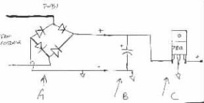
"IF I do this, I will plan to use the existing bridge. The rest of "
Yeah, if your bridge is functioning correctly, and producing dc voltage, that is all you need.. no need to purchase another bridge.
"the circuit is simple, but you started out recommending 7812 regulators, then changed that to 7815 - is this a 15volt "
I had originally thought that only 7812's ( 12v positive regulator ) were available, but found that there is the possibility that some people will carry a 7815 ( 15 positve reg. )
The 7812's would work ok, but your charging voltage would only be 12... it would be prefered to be a bit higher, but 12 would get you by. As a way to float it a bit, a small value resistor can be added between the grnd ref. of the regulators and ground to give you a slightly higher output voltage. Not exactly the best way to go about it, but what the heck.
If you can get your hands on the 7815 or equivalent.. they will be more suited. Some may argue that 15 is too high a charging voltage, and in some cases I will agree.. some sensitive electronics may not tolerate much above 14.5... seems funny.. but that .5 volt can sometimes make a difference to a marginal piece of equipment. If 15v is a problem, still use the 7815's, but inline with the output, put a couple of the 6amp/50piv diodes i mentioned in series.. the will have a forward voltage drop from their junctions, and will drop the charging voltage down to a more reasonable level. Also, this is less 'black magic' than the resistor in the ground reference for the 7812's, as some vregs don't like artificially inflated reference.. ( makes fryodes outta them.. or SMD - smoke emitting diodes /w3tcompact/icons/smile.gif ). The diodes in line with the 7815's actually form a circuit known as a constant current regulator, especially since you have a fixed source, that has a limited, pre-determined output ( dynamo ). The 7812's and 7815's can do up to 1.5 amps... 5 should be plenty.... just parallel them.. the diodes ( if you use them ) are rated to 6 amps, again... gives you 1a of tolerance if it is indeed a 5a charging system. Parallel two, then add another set of 2 paralleled, in series... 4 diodes ( 2 paralleled, and two parralleled... allows for 12amps current, and gives you 2 forward junctions to overcome for voltage drop.
""regulator? Then you recommended I "add an epoxy rectifier or two in line with the output (constant current regulator via diode junction)". What is all this and is it necessary. Can I just substitute the 7815 for the 1812 or do I then end up with a 15volt regulator, and that would be too much? As I remember it, when the battery was new, I measured it at 15volts.""
I changed my mind on the epoxy rectifiers, as I havn't seen any lately on the shelf that handle more than 3amps... the other ones I listed will do 6a.. and are sold in a 4 pack for like 2.99.
""Putting a resistor between the ground reference of the 7812 and ground increases the zero reference voltage and therefore increases the regulated output voltage relative to ground? That would allow me to "tune" in the regulated voltage - right?""
Youre on the right track. Sometimes they get alergic to this, and emit smoke... 7815's will be better if you can get them.
"Also, you indicate that the capacitor should be 100uF or better. You mean a minimum of 100uF and that a 120uF or 150uF would be better? How high should I go?"
Sure.. for dc power supplies.. bigger is *generally* better when filtering.. I wouldn't go overboard though.. in a high load situation, you'll have an averaging effect anyway. don't go over 1000u unless you get a good deal.. sometimes you find an assortment with a 2200u or a 4800u or even a 6000u in there as a goody.. but most of the big ones have a tolerance of like 15-16v.. so you need to hit somewhere around a 25v tolerance to give you some built in design failure protection.
"By the way, component availablity isn't a problem. We have a number of guys here at work who build little prototype circuits all the time. I'm sure I can have them get any of these parts for me."
That is excelent! wish I had friends like that.
Sounds like you are off to a good start.
Soundguy