3RRL
Super Member
- Joined
- Oct 20, 2005
- Messages
- 6,931
- Tractor
- 55HP 4WD KAMA 554 and 4 x 4 Jinma 284
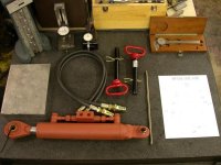
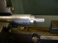
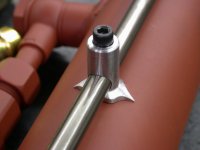
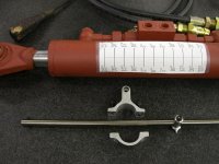
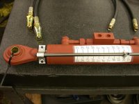
I just received my Top & Tilt hydraulic cylinder and hoses from CCM and decided to make a level gauge for operating the boxblade. The gauge is made up of a bracket that clamps to to the cylinder rod by (2) 10-32 socket head cap screws, an indicator tip that tells what position the box blade is in, and a rod for the indicator tip to slide on. The tip is adjustable and can be fastened to the rod by a 10-32 socket head cap screw. The 3/8"Ø rod is about 12" long an is bolted to the cylinder bracket. Last, I made a mock degree chart that tells me how much the boxblade is tilted frontwards or backwards. Keep in mind that it is only a mock chart for show and tell at this point. When I bring the system to my tractor this next week, I'll have to mark the cylinder correctly.
I plan on setting the boxblade level and mark the 0° there and move the indicator tip to it.. Then tilt each way and measure the boxblade until I get it to 5° and mark the cylinder there...and so on and so on. Then I'll make a neat chart on my computer at home.
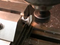
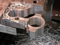
I machined all these parts this afternoon out of billet T-6061 Aluminum, so I just got done with them. I drew a CAD design first so it would fit properly.
I'm going to post several pictures of the parts. Hope you like them and I hope they'll work OK. This first one is of all the components.
