Custom Made Level Gauge for Top & Tilt

   / Custom Made Level Gauge for Top & Tilt #1  

3RRL

Super Member
Joined
Oct 20, 2005
Messages
6,931
Location
Foothills of the Giant Sequoia's, California
Tractor
55HP 4WD KAMA 554 and 4 x 4 Jinma 284
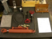
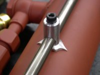
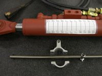
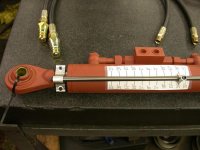
I just received my Top & Tilt hydraulic cylinder and hoses from CCM and decided to make a level gauge for operating the boxblade. The gauge is made up of a bracket that clamps to to the cylinder rod by (2) 10-32 socket head cap screws, an indicator tip that tells what position the box blade is in, and a rod for the indicator tip to slide on. The tip is adjustable and can be fastened to the rod by a 10-32 socket head cap screw. The 3/8"Ø rod is about 12" long an is bolted to the cylinder bracket. Last, I made a mock degree chart that tells me how much the boxblade is tilted frontwards or backwards. Keep in mind that it is only a mock chart for show and tell at this point. When I bring the system to my tractor this next week, I'll have to mark the cylinder correctly.

I plan on setting the boxblade level and mark the 0° there and move the indicator tip to it.. Then tilt each way and measure the boxblade until I get it to 5° and mark the cylinder there...and so on and so on. Then I'll make a neat chart on my computer at home.

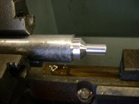
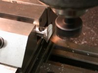
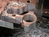
I machined all these parts this afternoon out of billet T-6061 Aluminum, so I just got done with them. I drew a CAD design first so it would fit properly.

I'm going to post several pictures of the parts. Hope you like them and I hope they'll work OK. This first one is of all the components.
 

Attachments

  • 773619-COMPONENTS.JPG
    773619-COMPONENTS.JPG
    85.4 KB · Views: 902
   / Custom Made Level Gauge for Top & Tilt
  • Thread Starter
#2  
This pictures shows how I started to turn the indicator tip in the lathe.
 

Attachments

  • 773622-INDICATOR IN LATHE.JPG
    773622-INDICATOR IN LATHE.JPG
    63.3 KB · Views: 666
   / Custom Made Level Gauge for Top & Tilt
  • Thread Starter
#3  
Then I put it in the milling machine and drilled and reamed the hole for the rod and tapped it. Here I'm flycutting the concave radius to match the OD of the cylinder.
 

Attachments

  • 773623-MILLING INDICATOR.JPG
    773623-MILLING INDICATOR.JPG
    68.4 KB · Views: 547
   / Custom Made Level Gauge for Top & Tilt
  • Thread Starter
#4  
This picture show the indicator tip mounted on the steel rod. Note that I machined "arrows" on each side of it. These will point to the degree marks on the cylinder later.
 

Attachments

  • 773625-INDICATOR ON SHAFT.JPG
    773625-INDICATOR ON SHAFT.JPG
    50.1 KB · Views: 580
   / Custom Made Level Gauge for Top & Tilt
  • Thread Starter
#5  
Then I started to machine the bracket that clamps on to the cylinder shaft. I also drilled and tapped it and bored out holes that fit the 3/8"Ø rod and the cylinder shaft. I don't have a CNC in the garage so I had to free form cut the OD. Later, I cut it down the center of the large hole to make the clamp section.
 

Attachments

  • 773626-MILLING CYL BRACKET.JPG
    773626-MILLING CYL BRACKET.JPG
    91.5 KB · Views: 504
   / Custom Made Level Gauge for Top & Tilt
  • Thread Starter
#6  
Here are all the parts ready for assembly...Hope it goes together.....YIKES

Notice the mock degree chart I taped on the cylinder for you guys to see.
 

Attachments

  • 773628-READY FOR ASSEMBLY.JPG
    773628-READY FOR ASSEMBLY.JPG
    84 KB · Views: 580
   / Custom Made Level Gauge for Top & Tilt
  • Thread Starter
#7  
And finally...
Here it is all together. WOW...Everything fits perfectly. There is about .040" clearance between the indicator tip and the body of the hydraulic cylinder. I can get accurate readings to the chart this way.
Now to mount it all up and do the final calibration when I go up this week to vist my tractor.
Thanks,
 

Attachments

  • 773630-LEVEL GAUGE MOUNTED TO CYL.JPG
    773630-LEVEL GAUGE MOUNTED TO CYL.JPG
    89.8 KB · Views: 697
   / Custom Made Level Gauge for Top & Tilt #8  
Well, nice thought and design.

However, you were not the first to come up with the idea. The Integration Engineering TCC setup had cylinders with a very similar gauge and indicator setup. CCM also sold them. Attached is a picture taken from the CCM web site.
 

Attachments

  • 773695-Sidelink.jpg
    773695-Sidelink.jpg
    27.2 KB · Views: 635
   / Custom Made Level Gauge for Top & Tilt #9  
3RRL, nice job. Very well thought out and designed and a plus because you got to put your machinery to good use. I have a machine shop set up also and I enjoy working in it when I get the time. There is always great satisfaction when you build something yourself.
 
   / Custom Made Level Gauge for Top & Tilt
  • Thread Starter
#10  
</font><font color="blue" class="small">( Well, nice thought and design. However, you were not the first to come up with the idea.)</font>

Thank you...??
Having copied the idea directly from one of the pictures I saw on the CCM website made me realize that I'm not the first one to come up with that idea. /forums/images/graemlins/grin.gif That's also where I bought the cylinder but it did not come with the level system on it. So I made my own.

Surely wasn't trying to imply or take any credit for it. I was just sharing my project. In fact, that statement probably applies to 99% of the projects the guys on this forem do to their tractors/property/barns/lakes etc. But thanks for pointing that out to me.

A buddy of mine suggested to mount a laser level and then put a readout on my instrument panel. Sounds pretty interesting regardless. I might try that for the Front loader when I get back?
Anyway, it was a lot of fun... and I got to use my garage machinery too.
 

Tractor & Equipment Auctions

2014 Chevrolet Impala Limited Sedan (A48082)
2014 Chevrolet...
Toro 30495 Groundsmaster 7200 72in Zero Turn Mower (A48082)
Toro 30495...
2014 Audi Q5 AWD SUV (A48082)
2014 Audi Q5 AWD...
2803 (A50460)
2803 (A50460)
2011 Ford Crown Victoria Sedan (A48082)
2011 Ford Crown...
2013 VOLVO VNL860 TANDEM AXLE SLEEPER (A51219)
2013 VOLVO VNL860...
 
Top