Custom UTV

   / Custom UTV #61  
The picture I showed was from a low slung hot rod. Many coil sprung 4x4's use them and they are then above the axle. Range rover being one of the first examples, except that they had a slightly more complicated 3rd arm in the middle with a fancy ball joint. But it again only worked because they had a rigid axle connecting the 2 wheels together.

You can't use a motorcycle rear trailing arm design on a 4 wheel vehicle. Motor cycles lean into corners so they do not have side loads the way a 4 wheel vehicle will have which does not lean. The motorcycle style design would quickly be destroyed in your application. You need to have your suspension design absorb all lateral and torsional forces. That could be all of the vehicle weight on 1 wheel at a 45 degree angle in some cases. Not exaggerating..

The simplest solution would be to use something like a straight trailer axle (2 hubs connected by a straight tube), use 2 radius rods like what you have in mind + 1 panhard rod behind the tube of the axle. The radius arms control the fore and aft forces, resist the torsion of the drive system and braking as well as the vertical suspension reactions. The panhard rod controls any lateral movement. Your radius arms would just have to attach to the top and bottom of the axle "tube" to be able to resist the torque. You may be able to get such radius arms ready to go from a vehicle like the Land rover. This is what they look like
TF508.jpg
 
Last edited:
   / Custom UTV #62  
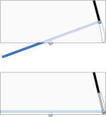
What if you made a tilt deck similar to this one with a vertical cylinder (or cylinders) in the front corners to lift it up?
You could add a flip up front with a pair of cylinders up there if you needed a longer ramp or something to restrain your chair.
Speaking of which, how are you planning to planning to keep your chair in place as you are bouncing and rocking around?

Aaron Z
 
   / Custom UTV
  • Thread Starter
#63  
The picture I showed was from a low slung hot rod. Many coil sprung 4x4's use them and they are then above the axle. Range rover being one of the first examples, except that they had a slightly more complicated 3rd arm in the middle with a fancy ball joint. But it again only worked because they had a rigid axle connecting the 2 wheels together.

You can't use a motorcycle rear trailing arm design on a 4 wheel vehicle. Motor cycles lean into corners so they do not have side loads the way a 4 wheel vehicle will have which does not lean. The motorcycle style design would quickly be destroyed in your application. You need to have your suspension design absorb all lateral and torsional forces. That could be all of the vehicle weight on 1 wheel at a 45 degree angle in some cases. Not exaggerating..

The simplest solution would be to use something like a straight trailer axle (2 hubs connected by a straight tube), use 2 radius rods like what you have in mind + 1 panhard rod behind the tube of the axle. The radius arms control the fore and aft forces, resist the torsion of the drive system and braking as well as the vertical suspension reactions. The panhard rod controls any lateral movement. Your radius arms would just have to attach to the top and bottom of the axle "tube" to be able to resist the torque. You may be able to get such radius arms ready to go from a vehicle like the Land rover. This is what they look like
TF508.jpg

I can't have anything underneath the machine, there just won't be enough ground clearance if I do, because the front-end kneels down almost 8 inches, to allow the chair in and out. Unless I'm misunderstanding you
 
   / Custom UTV
  • Thread Starter
#64  
What if you made a tilt deck similar to this one with a vertical cylinder (or cylinders) in the front corners to lift it up?
You could add a flip up front with a pair of cylinders up there if you needed a longer ramp or something to restrain your chair.
Speaking of which, how are you planning to planning to keep your chair in place as you are bouncing and rocking around?

Aaron Z

I've tried the tilt bed, and lowering floor ideas several times. But they just don't seem to work very well with a small amount of space inside the machine. It looks much more functional on a large flat surface like a trailer. There are a number of different electric tiedown systems that I can purchase. I haven't decided exactly what yet. But that's the last my concerns, I just want to have something that moves.
 
   / Custom UTV #65  
kdlklm said:
would that not affect my ground clearance, I want to keep the middle as open as possible. One thing I have looked at is a single-sided swing arm that are used on motorcycles. I could build something like that.

Yes this is what I'm talking about. Same as the sketch I attached. The arms should attach to a tube that runs the width of the vehicle. This will be very strong. Not sure what you would use for bearings though....
 
   / Custom UTV #66  
I've tried the tilt bed, and lowering floor ideas several times. But they just don't seem to work very well with a small amount of space inside the machine. It looks much more functional on a large flat surface like a trailer.
What if you made an arc shaped slit in both sides and had a rod stick through to connect to a pair of rams?
Something like:
TiltDeck.png

There are a number of different electric tiedown systems that I can purchase. I haven't decided exactly what yet. But that's the last my concerns, I just want to have something that moves.
Makes sense.

Aaron Z
 
   / Custom UTV
  • Thread Starter
#67  
going with an air ride system will kill two birds with one stone, it will give me suspension and allow the front-end to kneel down. Plus there's an option for a self leveling system. Which would be nice on slopes. The cost of the air ride system is making me simplify the system.
 
   / Custom UTV
  • Thread Starter
#68  
Yes this is what I'm talking about. Same as the sketch I attached. The arms should attach to a tube that runs the width of the vehicle. This will be very strong. Not sure what you would use for bearings though....

I see which are saying, I just need to find a way to get it passed the brackets and the shock absorber.
 
   / Custom UTV #69  
OK, this picture shows the old layout with 2 radius arms + the triangular upper arm (which would be replaced by the panhard rod). If you imagine the coil springs being replaced by air bags, the basic idea would fit. These vehicles have at least 8" of articulation.

So in your case the hardware is simplified. Instead of an axle/differential, you have a tube. You have 2 side mounted radius arms, like what you originally had in mind, just the pivot has to incorporate a pair of elastomeric bushings to allow for some lateral movement. Most leaf sprung vehicles have these bushings for the same reason, the leaf spring has to twist when one wheel is raised and not the other. There is 1 panhard rod connected to the chassis on 1 side and the axle tube on the other side. So now the axle can go up and down and is constrained side to side and is very strong.

Somewhere, you still need drive to the wheels, and the means to allow the wheels on one side to turn faster than the other side when turning. Using a small axle from passenger car could be a relatively simple solution, you drive the differential with a hydraulic motor and it already provides the differential action. Its a pity I have no cad system at home, since whipping up a design like this would not take long.


IMG_5578.JPG
 
   / Custom UTV
  • Thread Starter
#70  
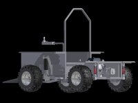
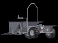
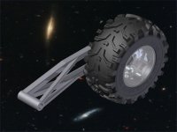
I made a few changes to the pivot arms, I added some more bracing to help the sideload when turning and being on slopes. just looking for some feedback as to whether it will be strong enough or not. The main shaft in the back that holds it all together, is 1.5 inches. It goes completely through the back of the machine to the other side.
 

Attachments

  • air ride suspension.jpg
    air ride suspension.jpg
    45.8 KB · Views: 262
  • air ride suspension2.jpg
    air ride suspension2.jpg
    43.4 KB · Views: 276
  • air ride suspension3.jpg
    air ride suspension3.jpg
    68.4 KB · Views: 359
  • air ride suspension4.jpg
    air ride suspension4.jpg
    58.2 KB · Views: 245

Tractor & Equipment Auctions

CFG MH12RX Mini Excavator (A49461)
CFG MH12RX Mini...
Turfco Mete-R-Matic III Pull-Behind Top Dresser (A51691)
Turfco...
William Nash HB-1030 10ft Hy-Brid Electric Scissor Lift (A50322)
William Nash...
5' X 20' 3/8" THICK STEEL PLATE (4) PIECES (A51244)
5' X 20' 3/8"...
2015 Jeep Compass Latitude SUV (A50324)
2015 Jeep Compass...
2023 Club Car Carryall 700 Utility Cart (A51691)
2023 Club Car...
 
Top