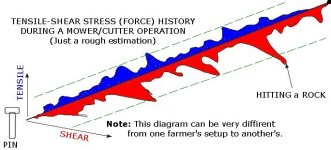
I drew a simple diagram for stress history on a pin during an operation (see attached picture.) This is just a rough estimation, but can still be close to the reality because tousands of such diagrams (for each farmer's setup/field/operation) can be drawn, and each of these diagrams can be different than another one.
What we are sure here in this diagram is that pin stress/force history diagram shows us a "chaotic" history in which sometimes a peak in shear may occur (for ex., when hitting a big rock), sometimes a small peak in tensile stress may occur due to a sudden ground depth change.
A shear pin which can resist all these stresses could be made easily. But there is a restriction; You DO want it to be broken after a certain stress/force value because you do not want to hurt your PTO/Engine/etc. It is this restriction that makes the problem/design very difficult. Why? Let me explain. Lets say the green dashed lines show operating range of shear pin. Now, 2 big questions to be answered:
(1.) Are all stress history diagrams of all farmers operations "more or less" same? Roughly similar diagram form isn't acceptable because this diagram is a chaotic diagram with a forms/peaks depending on each farmer's field/operation. Okay, LETS SAY you determined an average curve/diagram which will represent all farmers' pins at different fields/operations. Then, go to (2).
(2.) Where will the green line (pin working range) on this diagram be? The position of this green line depends on your pto+engine+attachment setup and the condition of this setup. A good quality pto+engine+attachment gearbox in a good condition can even cover all those stress peaks in this diagram. If they are old and in bad condition, this green line will be go toward the zero stress axis.
So, there are many variables (chaos, condition of pto+gearbox+etc, etc etc.) So? What can be done? Only and only one thing; This stress diagram should be drawn for EACH field/operation. And, the green line should be located on this diagram according to each special system (pto+gearbox+etc.)
It may look like a very complicated work, but I already proposed very simple method which can be applied by EACH of farmer ONCE for their EACH new implement they buy. It's a SPECIAL SPECIMEN (maybe, made of aluminum.) With this test specimen, you will automatically set the position of your own green line. With such a prototype pin in this green line range, your pin will break only when it approaches to a stress level which can give a damage to gearbox/pto/etc.
PS: Stress Fatique in the pin is another problem, but it's less important because anyways we aren't worrying about breaking the pin after a long period and the frequence/cycle in this stress diagram isn't so high to take the fatique into consideration.