Double Pilot Operated Check Valve for 2 Cylinders???

   / Double Pilot Operated Check Valve for 2 Cylinders???
  • Thread Starter
#21  
MJPetersen said:
What I was thinking is that the whole thing would be above the rear flap and not interfere with the operation of it at all. I did not get a photo today, maybe tomorrow.

Mike


Mike, thanks, I understand what you are saying now.
Will take a look at it from that vantage point.

thanks, John
 
   / Double Pilot Operated Check Valve for 2 Cylinders??? #22  
OK I took some pics today and maybe now I can better explain "o co chodzi". :eek: :D

In the pics that I saw of the KK tiller there are rear diag braces. I was thinking that you could put your pivot for your wheel mechanism behind those rather than like mine (which is right behind the box). From there the mechanism with the wheels reaches even further toward the rear and an actuating arm comes up from the pivot area but connected to the wheel mechanism. One end of the cylinder connects there and the other end connects in the 3pt tower. My Yanmar tiller has rear steel wheels. The wheels control the depth of the tiller through the action of a turnbuckle like screw. Well just look at the pics and I think that you will understand what I was thinking--Whether it is good or not is for you to decide--it is your tractor and tiller not mine. :rolleyes: :D

Let me know what you decide and how you do it. I am curious.

Mike
 

Attachments

  • YM tiller side.jpg
    YM tiller side.jpg
    122.5 KB · Views: 200
  • YM tiller above1.jpg
    YM tiller above1.jpg
    95.2 KB · Views: 189
   / Double Pilot Operated Check Valve for 2 Cylinders??? #23  
Hey Skunk,
Do you have any good pictures of your tiller? Looks like in the pictures of the depth draft wheels Mike posted, they are behind the tiller too? Sort of what my gauge wheels would do.

Do you have the KK Model# TG-60-Y that has those skid shoes on each side?
How much adjustment/movement are you looking for?
 
   / Double Pilot Operated Check Valve for 2 Cylinders???
  • Thread Starter
#24  
MJP, thanks for the pics!!
I now recognized the Yanmar tiller set-up, I've seen them before.

I was going to try to stick with the KK's original skid design, and raise and lower the skids, near or AT the point where the bolted adjuster now exists.
See this pic for the KK (Not mine, but a pretty good pic showing the KK's configuration)
KK Tiller on a BX

As you and others have said, a linkage arm could be used as the connecting link down to the skid, connected to a "JackShaft" of sorts, rotated by the hydraulic cylinder.

I looked at the propects of mounting the rotating shaft in back, just above the rear flap door, as you described, and it could be done. Will need a 5 foot section of pipe with a decently thick wall. I may have some commercial sprinkler pipe, that may work.

Still wrestling with the cylinder location, though.
I hear what you are saying about using the 3PT A frame as a mount point.
That assembly is currently designed to be unbolted, so, i don't want to weld in such a way it becomes permanent, which may mean welding flanges, and bolting on a bracket to hold the cylinder.

Still pondering....no hurry.
 
   / Double Pilot Operated Check Valve for 2 Cylinders???
  • Thread Starter
#25  
3RRL said:
Hey Skunk,
Do you have any good pictures of your tiller? Looks like in the pictures of the depth draft wheels Mike posted, they are behind the tiller too? Sort of what my gauge wheels would do.

Do you have the KK Model# TG-60-Y that has those skid shoes on each side?
How much adjustment/movement are you looking for?

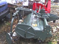
Rob, I have the TG 48", but same exact config. with the skids.
I had wanted to keep from adding wheels in the back, as they would roll over the freshly tilled soil, I do more landscaping and raised beds than general tilling for planting, so, leaving a pristine tilled path is desireable in my case.
That's why I was sticking with the skids.

See the picture link I posted above, Mine is set just like that one, middle bolt hole. That gives above 4" or so of tillage depth. So let's call it the Mid-point.
I'd like to get from 0" to 8" , if possible. i think the KK is rated up to 9" deep, but, I can always move the front bolt down, as I would think that gives the last little bit of depth.

Something like your wheel mechanism design could still work, just imagine it separated to each side, with a linkage to the skid, rather than a wheel.

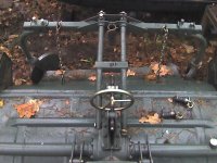
Overall, the top of the KK tiller is not condusive for a straight forward design. Most of the design will need to focus on missing the many obstacles, (Gear box, Shaft, 3 Pt. supports) while not becoming a complicated rube-goldberg type of set-up.

I've been doodling and sketching to see what I can come up with.

I'm still liking the idea of dual cylinders, one mounted on each side from the skids up to the Top edge where there is more than enough thick angle steel to mount the cylinder clevis. The dual cynlinder design is straight forward and cuts down on a lot of fabrication steps and totally avoids the issue of obstacles on top of the tiller.

I have been beefing about the additional cost for another cylinder, but, by the time I buy the additional metal and fabricate, the extra money for the 2nd cylinder probably isn't as big a show stopper for the dual design as I originally thought.

Still pondering which direction to go.
 
   / Double Pilot Operated Check Valve for 2 Cylinders??? #26  
SkunkWerX said:
I was going to try to stick with the KK's original skid design, and raise and lower the skids, near or AT the point where the bolted adjuster now exists.

Oh !:eek: I must have slept through that lecture!!

Mike

PS. I looked at the picture and I have a new -- if not better idea. What if you mounted the cylinder cross wise above the rear square tube? Then with linkages you could get the movement that you want.
 
   / Double Pilot Operated Check Valve for 2 Cylinders??? #27  
I'm still liking the idea of dual cylinders, one mounted on each side from the skids up to the Top edge where there is more than enough thick angle steel to mount the cylinder clevis. The dual cynlinder design is straight forward and cuts down on a lot of fabrication steps and totally avoids the issue of obstacles on top of the tiller.

Yeah, I see what you mean.
I was going to sketch up an idea much like Mike just said. Lay one cylinder horizontal and use linkage and pivots to activate the skids. But that is a lot of fabrication and you'd need to buy a bunch of steel for the linkage itself, but also for the mounts and pivot braces needed. I know from my Quick Attach Wheel Mount project.
Dual cylinders would be easy to do with only 1 mount for each one.

You connect the rod to the end of the adjustable bar, except remake that bar so it is fastened like a dovetail or "T" slot and powered by the cylinder... so it slides up and down.

My only concern with that is there is no way to balance them other than by theory. If for some reason one cylinder finds more resistance than the other, connected parallel, the one with less resistance will move more in real life.

That's why loader cylinders work because they have the bucket (which connects the two) which forces them to work together....making them seem to work equally. But if you take the bucket off, they will move independently, depending on which has more resistance. I think you saw that thread where those grapples that attach to each loader arm separately (for log work?) and not connected to each other.

My guess would be you'd need to make a detent like stop in the sliding rail so each one can reach that same point before going past it. A good size detent and spring loaded plunger could work for that. The DPOCV would hold them in place once they get there. Increments every inch or so? Or use 2 valves?
 
   / Double Pilot Operated Check Valve for 2 Cylinders??? #28  
3RRL said:
My only concern with that is there is no way to balance them other than by theory. If for some reason one cylinder finds more resistance than the other, connected parallel, the one with less resistance will move more in real life.

That's why loader cylinders work because they have the bucket (which connects the two) which forces them to work together....making them seem to work equally. But if you take the bucket off, they will move independently, depending on which has more resistance. I think you saw that thread where those grapples that attach to each loader arm separately (for log work?) and not connected to each other.

My guess would be you'd need to make a detent like stop in the sliding rail so each one can reach that same point before going past it. A good size detent and spring loaded plunger could work for that. The DPOCV would hold them in place once they get there. Increments every inch or so? Or use 2 valves?


Only 2 ways I know of to synchronize cylinders. One way is with tensioning springs. Similar to what you see on a shop press. They provide enough physical tension to overcome the internal differences of each cylinder. Other way is with adjustable flow control valves. The latter being more expensive.
 
   / Double Pilot Operated Check Valve for 2 Cylinders??? #29  
Wayne County Hose said:
Only 2 ways I know of to synchronize cylinders. One way is with tensioning springs. Similar to what you see on a shop press. They provide enough physical tension to overcome the internal differences of each cylinder. Other way is with adjustable flow control valves. The latter being more expensive.
Hi Wayne,
We are on the same page then.
The spring loaded plungers and a detent will act like the springs you mentioned...imposing a load to allow sychronizing. Spring loaded plungers can be had with xxx amount of resistance to overcome. That would allow the second cylinder to get to the same place as the first one, assuming the 2nd one has less resistance than the plunger/detent offers to the first one.

I've never used the adjustable flow control valve method, nor the spring loaded plunger for that matter, but I'm sure it would work just like the springs you mentioned. I do use them frequently in the plastic injection molds I build for similar reasons, just not in hydraulics.

I'm assuming using the flow control valve method, their needs to be a predetermined resistance difference, and then that difference must remain constant, right? In other words, if that resistance varies due to some unforeseen obstruction, then the flow control valve needs to be re-adjusted.
For example, if both sides are synchronized with flow control valves at the beginning according to each individual resistance, if dirt or something gets in one side causing additional resistance or binding, then the valve would need re-adjustment.

Picking a spring loaded plunger and detent that say gives you 20lbs of resistance, the other cylinder would stop moving only if there was more than 20lbs resistance/binding on it. You could make a much heavier plunger/detent combo like 100lbs or more so as to compensate for the effect of grit or binding (up to the 100lbs in this example of course). With that in mind, the spring plunger/detent method would give you a range of varying resistance up to that amount, or say from zero to 100lbs.

The flow control method would not have that range, right? If one binds up exceeding the initial resistance used for setting them, the other keeps going. Unless there is some kind of flow tolerance or range that allows for unknown resistance, the spring method (which has a range) would be better right?
Please correct me if I'm wrong. I would be interest in learning how they operate and what the variances are once adjusted.

The question then is how much grit/binding do you plan for on a dirt engaging implement?
 
   / Double Pilot Operated Check Valve for 2 Cylinders??? #30  
I don't really know how the spring loaded plungers and detent would work. I'm not familiar with their operation.

The flow control valves would have plenty of adjustment to compensate for the changing physical characteristics of a wearing cylinder. They take a minor amount of playing with to get them set, but the guys I know with them use them quite frequently and rarely have to adjust them.

The spring loaded plungers you describe would work the same as an external spring, might even be a "cleaner" setup. Whatever way you provide the resistance, you are trying to load both cylinders equally so that they travel equally. Lets say you have two sister cylinders. One takes 50 lbs to move it, the other 55 lbs. If you used a 10 lb. spring, it would be plenty of pressure to overcome the internal differences. All you are trying to do is overcome the differences, not the total load.

Some of my customers use the spring set-up on three 5" bore by 8" stroke cylinders in a bluestone cutting application. They cut the bluestone like this because it makes a natural looking cut. There is a dull bar connecting the rods of all 3 cylinders. The springs overcome the internal differences and time the 3 cylinders perfectly. You would be surprised how small the springs are to control these big bore cylinders.

There is another way this can be done that I forgot about. You could plumb 2 different sized cylinders in series. If you get two cylinders, now you would have to do some math, and figure out the volume in the rod end of one cylinder. Find a cylinder with the same volume in the piston end. Hook them in series, and you have perfect cylinder timing with nothing added to ever break or go out of adjustment. It would be a weird setup, but with a minimal load, I wouldn't ever see a problem with this.
 

Tractor & Equipment Auctions

1973 POWER 30ft Pole S/A Towable Trailer (A48081)
1973 POWER 30ft...
2015 Ford F-250 4x4 Liftgate Service Truck (A48081)
2015 Ford F-250...
1000 Gallon Water / Chemical Tank (A50860)
1000 Gallon Water...
Segway i2 Personal Transporter (A48082)
Segway i2 Personal...
2007 MACK GRANITE ROLL OFF TRUCK (A51222)
2007 MACK GRANITE...
2008 Ford Crown Victoria Sedan (A48082)
2008 Ford Crown...
 
Top