I haven't updated here for a while mainly due to ill health and not being able to keep track of too much at one time. I have time now as I have a ruptured Achillies Tendon and so I am immobile!:smiley_aafz:
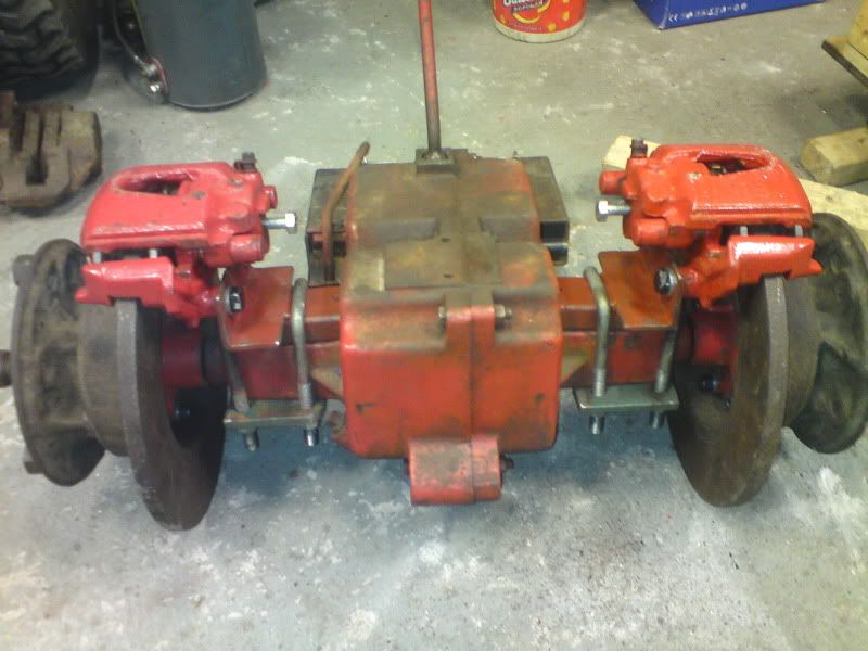
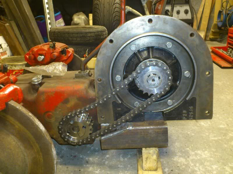
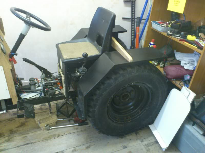
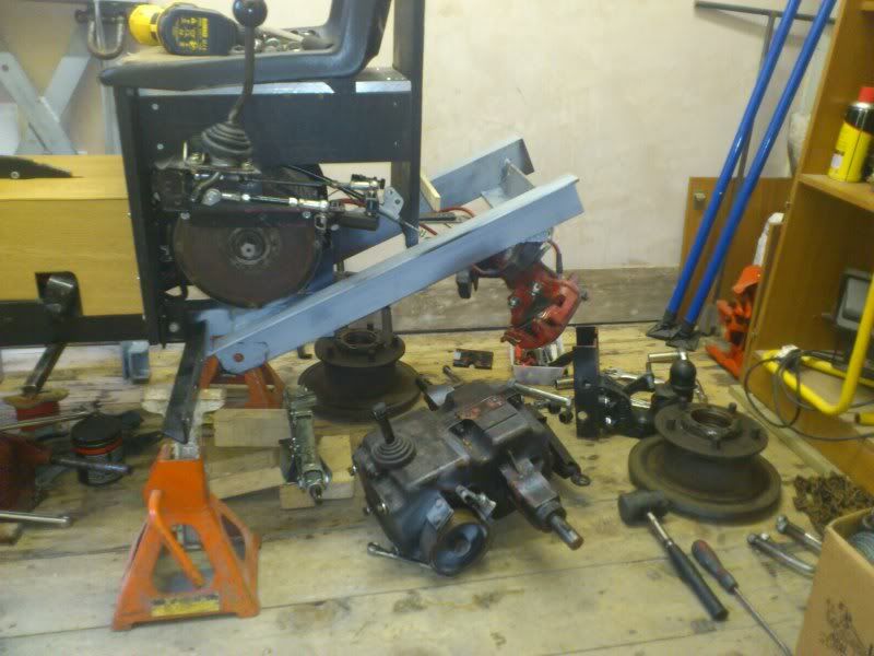
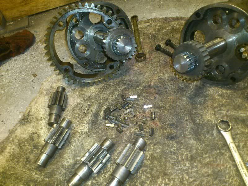
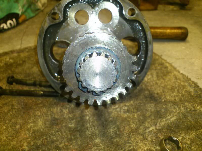
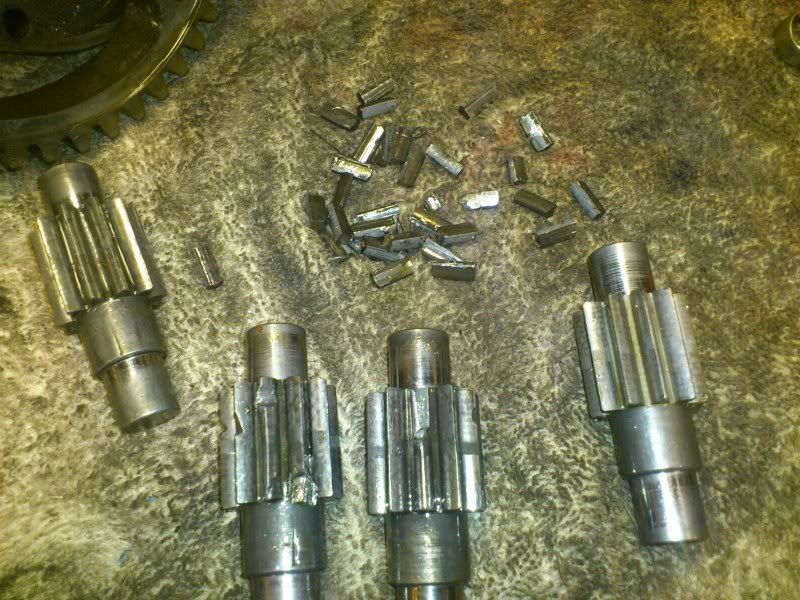
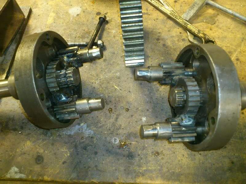
Anyway, the last photo was the broken diff in the first trans and a Wheelhorse 3F1R box ready to replace it.
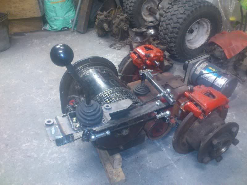
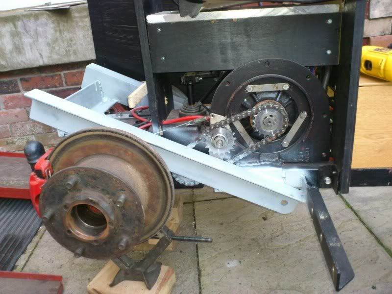
I converted it to disc brakes.
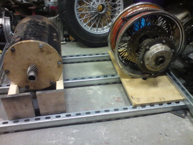
And then looked at fitting the 7" Clubcar motor.
Then decided on a bigger 9" fork truck motor!
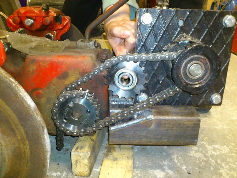
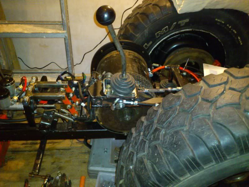
I relocated the gearshift from under my butt to my left side (being in the UK) and to a conventional H pattern instead of the sideways H pattern on the Wheelhorse.
I then cut off the rear of the tractor and grafted on the new frame and trans mounting.
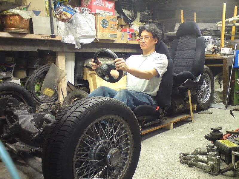
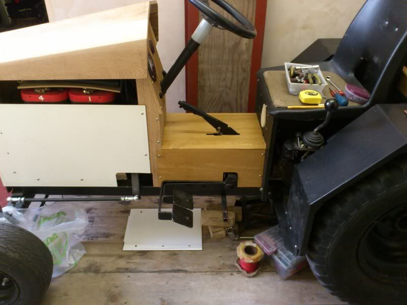
I moved the tractor from its home in my trailer into the house and started to reassemble it all in the warm and dry.
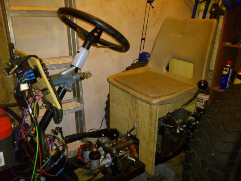
Added a temporary seat.
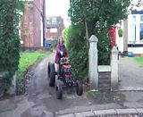
My partner then took it for a drive (video).
I then got a request to demonstrate it for some local organic farmers with a view to doing an electric conversion on their farm tractor!
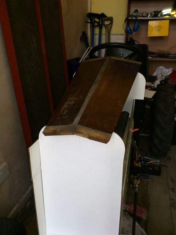
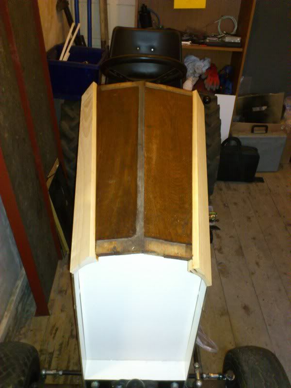
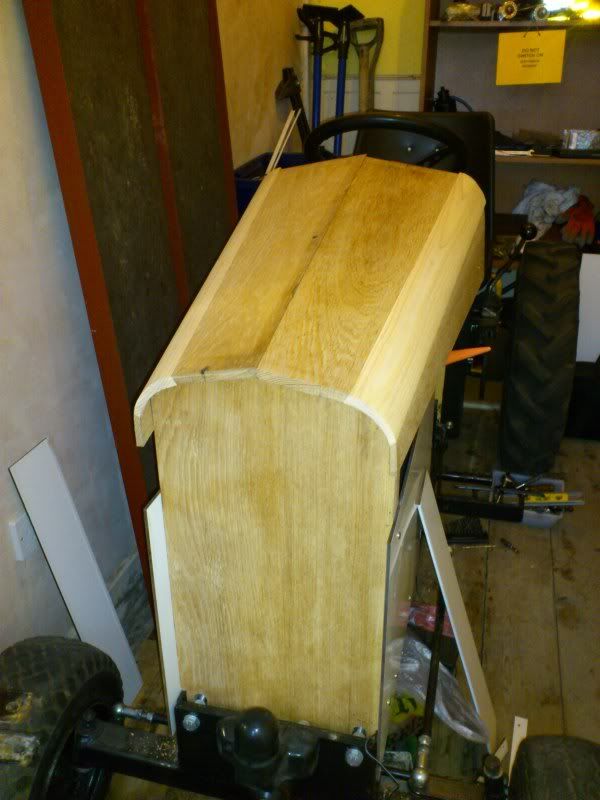
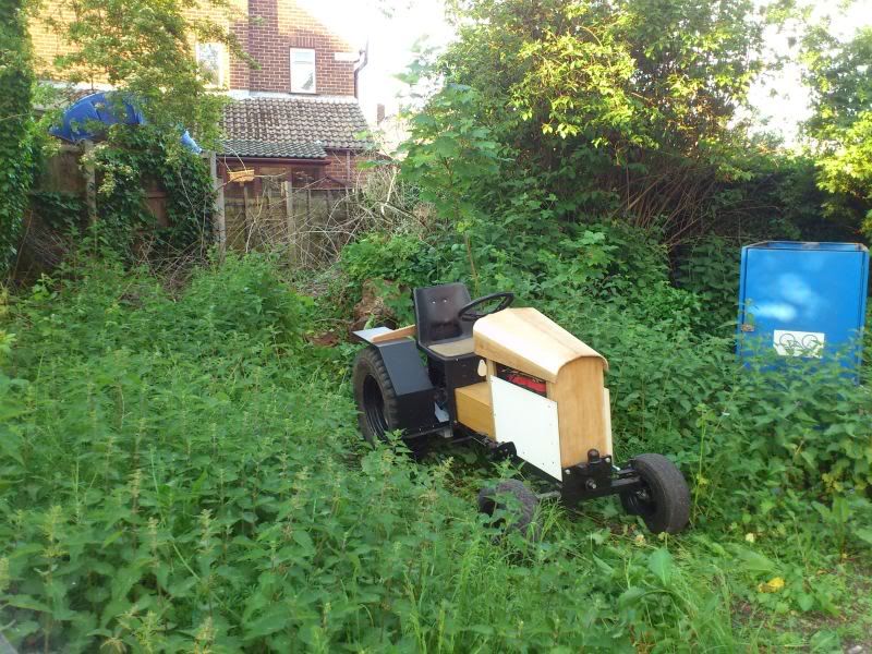
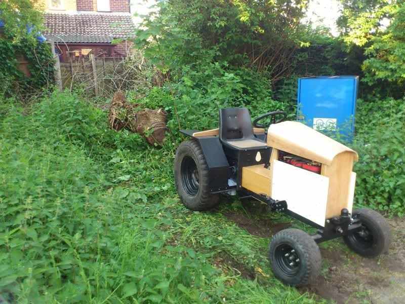
That meant I need to make it look a bit prettier so I started building some wooden body work in English oak and ash.
I ran out of timber for now so some bits are plastic.
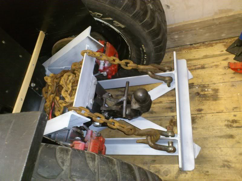
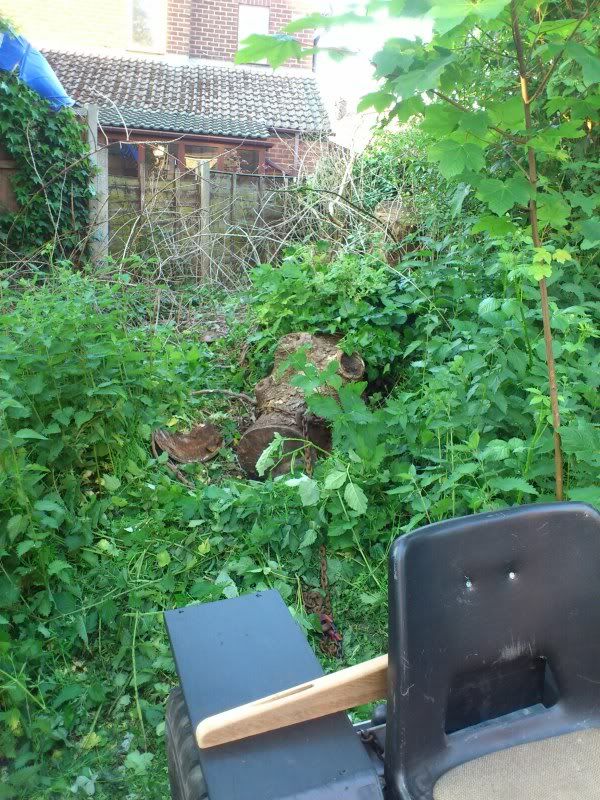
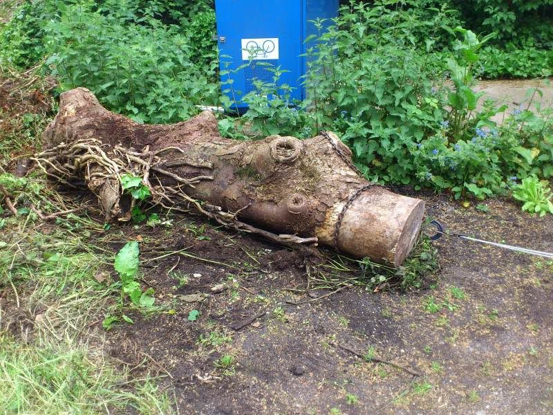
I then started on a ground anchor with a view to fitting a winch for timber hauling.
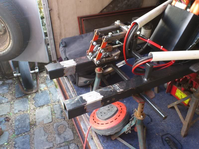
Chassis extension.
Anchor pinned to frame.