Electronic Flasher Circuit

   / Electronic Flasher Circuit #41  
Mark,
I finally got my hands on the schematic for the L3710 and will post that seperately when I match the scans together. Before I go any further I have to admit that Kubota has some pretty strange ways of documenting things[image]/w3tcompact/icons/eyes.gif[/image] As I am in the process of wiring up lights on the new canopy I also discovered how wimpy the factory wiring is /w3tcompact/icons/shocked.gif /w3tcompact/icons/mad.gif /w3tcompact/icons/shocked.gif. I even found a point where the main POSITIVE battery cable presses hard against the radiator frame (which my dealer confirmed had been the point of at least one fire that they know of). Not good news![image]/w3tcompact/icons/sad.gif[/image] Again, I will post pictures and suggestions once I am done with the project.

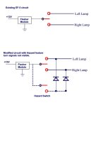
Now as to your flashers. Looking at the Kubota diagrams they do indeed switch the ground legs though a diode blocking arrangement so the you have right on, left on, or both on (hazard). Kubota uses three relays and a "hazard unit" [mystery device with 3 leads that looks like it could be an electronic flasher module as it is common with pin 3 of all 3 relays, pin 3 looks like the NO contact], one each for right and left and one for the flashers (at least according to the schematic - I have not needed to pull the instrument cowling off just yet to verify this).

Now, when I started writing this message I thought I had everything all worked out - but the more I checked your old messages the more confused I became!/w3tcompact/icons/crazy.gif How many relays do you have now (in the tractor - not in your possession). If I understood everything you have two electronic relays that are on-demand flasher modules with single outputs. Any conventional relays? any schematic of your current wiring?
 
   / Electronic Flasher Circuit
  • Thread Starter
#42  
Andy - I have only one flasher unit installed in the machine - a three-pin model with ground, 12v in, and 12v out terminals. That's it - no other relays, etc. I have a wiring diagram, but it's not right, because it shows hazard flashers, which I don't even have a switch for.

That's a bit shoddy, the way the battery terminal on your tractor is up against the frame. I assume you've corrected it...
 
   / Electronic Flasher Circuit #43  
OK, I'll draw up the circuit for one flasher and no relays (but it will most likely involve an additional relay or two).

It was the battery cable, not the terminal, which Kubota neglected. Interesting part was that as soon as I mentioned wiring and Kubota in the same sentence the service guys just /w3tcompact/icons/eyes.gif /w3tcompact/icons/eyes.gif /w3tcompact/icons/eyes.gif /w3tcompact/icons/eyes.gif /w3tcompact/icons/eyes.gif
 
   / Electronic Flasher Circuit #44  
Das Blinken Lights und Spits-n-Sparken

Mark, Finally finished diagramming the flashers. (I have to admit that the Kubota schematics are a bit wierd/w3tcompact/icons/crazy.gif )
OK, this first attachment has your original circuit as I understand it and below that a simple flasher circuit that overrides the turns signals. The diodes for this type of arrangment can be something like a Radio Shack 276-1185 full wave bridge rectifier (but you only use 3 of the four terminals and can use standard crimp- on connectors /w3tcompact/icons/smile.gif ). Either of these circuits are pretty simple - but wait till you see the next message "Kubota Style".
 

Attachments

  • 37-102458-TurnSignalCircuitsPage1.JPG
    37-102458-TurnSignalCircuitsPage1.JPG
    39.7 KB · Views: 1,406
   / Electronic Flasher Circuit #45  
Re: Das Blinken Lights und Spits-n-Sparken II

OK, now things get really strange./w3tcompact/icons/eyes.gif The attached is the Kubota method of providing turn signals and flashers.

When no turn signal is present, engaging the hazard switch causes the flasher module output to go through the normally closed contacts of the relays and flash both turn lamps. So far so good.

Now when you engage a turn signal normally (no hazards) the related relay closes and the lamp draws on the flasher module.

When both the hazard and the turn signal are engaged: the active turn signal remains connected to the flasher module output, while the inactive turn signal switches from the flasher module output to +12VDC (on but with very brief blinks when switching)./w3tcompact/icons/tongue.gif Trust me - this diagram is far simpler then the factory schematic./w3tcompact/icons/eyes.gif

Words of caution - I found the same relay I brought from my dealer for about 1/4 the cost in the Radio Shack catalog. ARGGHH! /w3tcompact/icons/blush.gif The only thing you may want to add is a fourth relay on the output of the flasher module so you don't have to worry about loading, though I suspect that won't be too much of an issue with the LED lamps./w3tcompact/icons/cool.gif
 

Attachments

  • 37-102462-TurnSignalCircuitsPage2.JPG
    37-102462-TurnSignalCircuitsPage2.JPG
    59.9 KB · Views: 2,960
   / Electronic Flasher Circuit
  • Thread Starter
#46  
Re: Das Blinken Lights und Spits-n-Sparken II

AndyR - Your muttering sounded phonetically like it was in German, when it should've been in Japanese... /w3tcompact/icons/laugh.gif

Ok, I think I pretty much understand what's going on as you diagrammed it. (You went to a lot of trouble to do that - thanks!) So are all those relays actually in the Kubota flasher? Or is the schematic's depiction of a flasher with 7 terminals just a misleading grouping of the flasher and the associated relays? And, if the flasher really is just an ordinary flasher and doesn't have 7 terminals, why do they want 50 bucks for it? (That last question is rhetorical, of course - at least as far as you're concerned....) Strange.
 
   / Electronic Flasher Circuit #47  
Re: Das Blinken Lights und Spits-n-Sparken II

Near as I can tell from my schematic (for the L3710) they are separate relays (and they show separate plugs for each). One of these days I will pull the shroud off of the instrument panel and take some pictures. The hazard unit (flash module) looks like a 3 pin device. Now if they were to combine a flasher and a relay - it would logically be about 7 pins... go figure.
 
   / Electronic Flasher Circuit
  • Thread Starter
#48  
Re: Das Blinken Lights und Spits-n-Sparken II

AndyR - Well, all I can say is, if they're charging 50 bucks and change for a plain old 3-pin flasher, they've got to be out of their minds.

I'm going back to studying your schematic some more... /w3tcompact/icons/smile.gif Thanks again...
 
   / Electronic Flasher Circuit #49  
Re: Das Blinken Lights und Spits-n-Sparken II

Actually it was $16. for a New Holland relay with mounting tab, rated at 30 Amps. Same thing at Radio Shack is about $3.99.
 
   / Electronic Flasher Circuit
  • Thread Starter
#50  
Re: Das Blinken Lights und Spits-n-Sparken II

AndyR - I can understand the difference in the relay prices (sort of), but I went to my local Kubota dealer and priced the Kubota Grand L flasher unit itself. It was $50 and change. That's the one I'm talking about. I didn't see one, though, so I don't know if it had 3 pins or 7.
 

Tractor & Equipment Auctions

Skidloader Trailer Mover (A47809)
Skidloader Trailer...
Truck Ladder Rack (A47809)
Truck Ladder Rack...
2012 STAGECOACH TRAILER MONORAIL (A47001)
2012 STAGECOACH...
2010 Gleaner 9250 Draper Head  30' with Crary Air Wind System (A46884)
2010 Gleaner 9250...
John Deere 6150M (A47307)
John Deere 6150M...
New Holland 3pt Finish Mower (A47809)
New Holland 3pt...
 
Top