OP
You are using an out of date browser. It may not display this or other websites correctly.
You should upgrade or use an alternative browser.
You should upgrade or use an alternative browser.
Finally ordered my TC45DA
- Thread starter TMAC
- Start date
- Views: 8525
/ Finally ordered my TC45DA
#81
OP
TMAC
Gold Member
OP
TMAC
Gold Member

OP
TMAC
Gold Member
markie61
Veteran Member
- Joined
- Mar 31, 2001
- Messages
- 1,362
- Location
- Northern Virginia
- Tractor
- 2019 Rural King RK55HC with Loader & Backhoe; 2001 New Holland TC40D with Loader
OK - I give up....
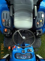
How did you get the overhead view...? /forums/images/graemlins/confused.gif /forums/images/graemlins/shocked.gif /forums/images/graemlins/crazy.gif
Mark
PS Pretty schweeetttt!
How did you get the overhead view...? /forums/images/graemlins/confused.gif /forums/images/graemlins/shocked.gif /forums/images/graemlins/crazy.gif
Mark
PS Pretty schweeetttt!
OP
TMAC
Gold Member
I stood on the top of the loader arms where they mount to the tractor. Dad always told me I had a little monkey in me. /forums/images/graemlins/shocked.gif /forums/images/graemlins/shocked.gif /forums/images/graemlins/shocked.gif /forums/images/graemlins/shocked.gif eeeeee!
OP
TMAC
Gold Member
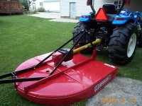
This morning the Blue Bird came at 9:30. The driver unloaded it off of a 40 foot roll back truck. I signed the papers and off he went but not before I quickly remembered I was supposed to get 5 extra shear pins with the Squealer and I noticed only one ignition key. He didn't have either with him and they weren't in the little tool box. So he told me to call in and remind the dealership. My dealer said he'd forgot about them and to stop by when I was around the area and he would take care of me.
So, that's good but, come this Sunday when I'm bush hogging I'll be a little frustrated if I shear a pin off hitting a stump or something /forums/images/graemlins/mad.gif. I should be all right though I've took that precaution of cutting the smaller stumps off to ground level and marker painted the ones I left standing a little extra taller. Oh well, I'm just happy she's/he/it's home. /forums/images/graemlins/grin.gif
So, that's good but, come this Sunday when I'm bush hogging I'll be a little frustrated if I shear a pin off hitting a stump or something /forums/images/graemlins/mad.gif. I should be all right though I've took that precaution of cutting the smaller stumps off to ground level and marker painted the ones I left standing a little extra taller. Oh well, I'm just happy she's/he/it's home. /forums/images/graemlins/grin.gif
Inspector507
Super Member
TMAC,
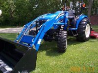
Looks great, now lets see some dust/dirt on 'er /forums/images/graemlins/grin.gif
Looks great, now lets see some dust/dirt on 'er /forums/images/graemlins/grin.gif
OP
TMAC
Gold Member
Will do Jerry as soon as I can get off work which won't be until Sunday and Monday. She'll probably be a mud puppy after the first time I take her over to the property but, maybe not. I have a small run off drainage from the farmers field next to my land that keeps the bottom kind of swampy where I cross to go back up into the field. That'll hopefully get fixed once the driveway gets put in and build up. /forums/images/graemlins/smile.gif
jinman
Rest in Peace
- Joined
- Feb 23, 2001
- Messages
- 20,387
- Location
- Texas - Wise County - Sunset
- Tractor
- NHTC45D, NH LB75B, Ford Jubilee
Greg, your tractor looks great! /forums/images/graemlins/cool.gif /forums/images/graemlins/cool.gif /forums/images/graemlins/cool.gif
I know you can't wait to get some seat time on Sunday. /forums/images/graemlins/smile.gif
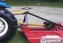
One thing I noticed from your picture that's a "pet peeve" of mine. It's the toplink float attachement they put on so many rotary cutters that needs just a couple of more engineering steps to correct a geometry issue. I've attached a close-up of the area in the attachment that shows what I'm talking about.
Yellow line: This is the problem. The float is over-center and in this position, when the tailwheel goes over a bump, the float linkage has nowhere to go. If you disconnect the toplink and extend it, you can put it over-center to the high side, but there's nothing to keep the toplink from ending up in this position the next time you lift the cutter with the 3PH. Gravity is your enemy here. /forums/images/graemlins/frown.gif
Orange and Blue lines: The orange line is my preferred minimum angle the toplink to float adapter would ever be allowed to achieve. With this limit, it would have the float range shown by the blue line and perform just as I want. /forums/images/graemlins/cool.gif /forums/images/graemlins/smile.gif
I just think there should be a stop welded on the float adapter so it will not go over-center and lock in the down position. Does anyone else share my frustration with this piece? /forums/images/graemlins/confused.gif I'm open to ideas if anyone has a good suggestion. In the meantime, I used a length of chain and and made a flexible limiter on my cutter. It allows just the movement shown by the blue line and works for me. Why these cutters can't have that engineered into this piece is puzzling to me. /forums/images/graemlins/frown.gif ...but lot's of things puzzle me. /forums/images/graemlins/blush.gif
I know you can't wait to get some seat time on Sunday. /forums/images/graemlins/smile.gif
One thing I noticed from your picture that's a "pet peeve" of mine. It's the toplink float attachement they put on so many rotary cutters that needs just a couple of more engineering steps to correct a geometry issue. I've attached a close-up of the area in the attachment that shows what I'm talking about.
Yellow line: This is the problem. The float is over-center and in this position, when the tailwheel goes over a bump, the float linkage has nowhere to go. If you disconnect the toplink and extend it, you can put it over-center to the high side, but there's nothing to keep the toplink from ending up in this position the next time you lift the cutter with the 3PH. Gravity is your enemy here. /forums/images/graemlins/frown.gif
Orange and Blue lines: The orange line is my preferred minimum angle the toplink to float adapter would ever be allowed to achieve. With this limit, it would have the float range shown by the blue line and perform just as I want. /forums/images/graemlins/cool.gif /forums/images/graemlins/smile.gif
I just think there should be a stop welded on the float adapter so it will not go over-center and lock in the down position. Does anyone else share my frustration with this piece? /forums/images/graemlins/confused.gif I'm open to ideas if anyone has a good suggestion. In the meantime, I used a length of chain and and made a flexible limiter on my cutter. It allows just the movement shown by the blue line and works for me. Why these cutters can't have that engineered into this piece is puzzling to me. /forums/images/graemlins/frown.gif ...but lot's of things puzzle me. /forums/images/graemlins/blush.gif