The tractor is starting beyond my expectations at this point, but it hasn't been below 20F either.
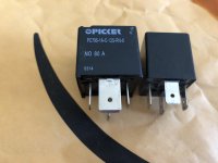
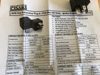
Two new 80 amp relays with the larger 3/8" tabs for the power side of the relay arrived today. 80 amps is overkill, but that is what I bought off amazon. Picker PC795-1A-C-12S-RN-X at $18.99 for the pair. They are sealed units, with nickel plated tabs and a resistor to protect the voltage spike that occurs when the field collapses.
The stock relay, Panasonic CB-1a-12V ACB33201 utilizes four - 1/4" female tabs with the following dimensions: 0.250 wide by 0.030" thick
The new relay has two-1/4" and two-3/8" tabs that measure 0.368" wide and 0.045 thick.
That's a 50% increase in thickness (0.030" vs 0.045")!!!
Note: Measurements taken with Starrett dial calipers
The thicker tabs should work significantly better with the mating female electrical connectors as they are designed for the wider male tabs.
I don't have time to install at this point, but plan on doing so in the near future. If nothing else I'm going to replace the other relay behind the dash that utilizes the same relay and mating socket to prevent any issues with poor continuity in the future.
The larger plastic housing is NOT an issue. There is plenty of room to accommodate the relay.
Perhaps the pictures will help show the size difference.
Kubota does sell a similar relay at the expected markup over what's available on the open market.
Here's a link to the relays if anyone is interested.
https://www.amazon.com/gp/product/B07GX6SXY2/ref=ox_sc_act_title_1?smid=A16HAOC7J321VG&psc=1
If you have any difficulty starting your tractor in cold weather, I highly recommend trying this type of relay as the thicker tabs should help improve continuity within the relay socket.