moship
Veteran Member
Recording this info in the event it helps anyone down the line.
Summary:
Glow Plugs: 19077-65512, 19077-65511, 19077-65510, 1J860-65510, 1J860-65510, 1J860-65511, 1J860-65512 are all linked as similar using Kubota's Illustrated Parts and Messick's.
GP price is different depending on PN. Surprising given they are functionally the same.
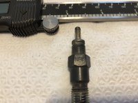
Kubota 19077-65512 is actually a NGK Glow Plug Part number: Y-716RS, stock number: 4693 (Rockauto has them for <$15)
GP Nut size: 7mm
GP itself: 12mm (deep socket)
NGK Data: https://www.ngkpartfinder.co.uk/files/NGK_Glow-Spec.pdf
The long story:
My tractor seemed to take a bit longer to start when cold (30F and below) than I thought it should. My expectation is it starts within 2-3 seconds of crank time. Anything longer seems unacceptable. It has always started, but I always questioned if the glow plug (GP) circuit was operating as designed and I questioned the short on time the dash calls for the GP to be energized. So it was time to investigate if all is functioning as it should with respect to the GP circuit.
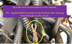
Started by ensuring the battery is fully charged. Battery terminals and connections cleaned using a wire brush or sandpaper to ensure good metal to metal contact. Fuel is recently purchased and Power Service (white) and biocide added every time.
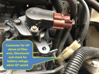
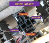
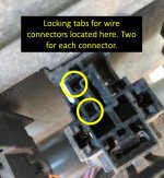
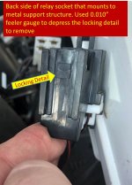
To measure supply voltage to the GP buss bar the GPs must be removed from the circuit. Otherwise you will not see battery voltage on the meter. On cab tractors there is a wire connector that can be disconnected and voltage measured at that point. (See photo) Great battery voltage is confirmed to the GPs.
Accessing GPs:
The nuts used to hold the buss bar to the GP are 7mm. They can all be accessed and removed using 1/4 ratchet with short and longer extensions. To keep from losing the nuts, a rare earth magnet was placed on the socket. Nuts are the flange type with knurling on the buss bar side, so no lockwashers are used. In some instances it was easier to access the GP's from the muffler side (left side).
With the buss bar removed from the GP the resistance can be checked against spec. Great all four are similar each other measuring approximately 0.9 ohms (within spec according to WSM).
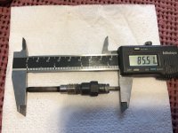
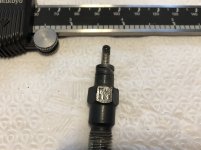
To visually inspect one GP was removed using 12mm deep socket. The GP looks to be in great shape. Sheath is clean, no blister or other overheat indications, terminals free of corrosion. Feel good about the appearance. Confirmed resistance again while it was removed. (Reference photo)
Decided to hook up the GP to fully charged battery to see how long it takes for them to glow. Wow! It takes approximately 4 seconds (at most) to see a very nice glow at the tip. Now I feel a lot more confident the short GP dash indication is justified.
Put everything back together and it starts as it should... Maybe a bit quicker - possibly due to the clean electrical connections or just a placebo effect.
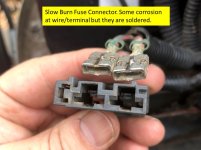
I really didn't find anything, but there was some evidence of slight corrosion at the GP buss bar white connector (maybe on cab models only), and it never hurts to clean the battery terminals including the chassis side of the battery ground. It does give me more confidence knowing the GP circuit is working as it should.
Tractor Model: L4740-3 HSTC
The stock Kubota glow plug (19077-65512) is actually a NGK part number: Y-716RS, stock number: 4693 (see photo). For reference: Kubota $31.71 Rock Auto $ 15.54
NGK can also be found at Napa or others. If you can't find it using the NGK part number, use the stock number.
In researching the current glow plug part number, I found a number of Kubota GP's are interlinked.
19077-65512 replaces 19077-65511 (Messick's) & 19077-65510 (Kubota's illustrated parts show 66512 = 66510)
Using 19077-65510 was replaced by 1J860-65510 which was replaced by 1J860-65510 $21.79 (Used Messicsk's to research 19077-66510)
1J860-655110 was replace by 1J860-65511 replaced by 1J860-65512 (Messick's)
The Kubota P/N (19077-65512) is used on the following models (according to Messick's great website).
The part fits the 90 models listed below:
KJ-S130D-USA, KJ-S150V-USA, KJ-S150VX-USA - 120601 NOZZLE HOLDER AND GLOW PLUG, KJ-S150VX-USA - 120602 NOZZLE HOLDER AND GLOW PLUG, KJ-T210V-USA, KJ-T210VX-USA - 120601 NOZZLE HOLDER AND GLOW PLUG, KJ-T210VX-USA - 120602 NOZZLE HOLDER AND GLOW PLUG, KJ-T270F-SW-USA, KJ-T270FX-SW-USA - 220601 NOZZLE HOLDER AND GLOW PLUG, KJ-T270FX-SW-USA - 220602 NOZZLE HOLDER AND GLOW PLUG, KX121-3ST (SN : 70000- / Super Series / Tier 4), KX161-3ST (SN : 70000- / Super Series / Tier 4), KX91-3S2 (SN : 40000- / Super Series / Tier 3)
L2800DT / HST (Dual Traction 4wd / Hydrostatic Transmission), L2800F (2wd),
L3200DT (Dual Traction 4wd), L3200F (2wd), L3200H (Hydrostatic Transmission),
L3240DT / GST (Dual Traction, 4wd / Glide Shift Transmission / Rops / 2007 - 2009), L3240DT-3 (Dual Traction 4wd / Rops / 2010), L3240F (2wd / Rops / 2007 - 2009), L3240F-3 (2wd / Rops / 2010), L3240GST-3 (Glide Shift Transmission / Rops / 2010), L3240HST (Hydrostatic Transmission / Rops / 2007 - 2009), L3240HST-3 (Hydrostatic Transmission / Rops / 2010), L3240HSTC (Hydrostatic Transmission / Cabin / 2007 - 2009), L3240HSTC-3 (Hydrostatic Transmission / Cabin / 2010),
L3400DT / HST (Dual Traction 4wd / Hydrostatic Transmission), L3400F (2wd)
L3540GST (Glide Shift Transmission / Rops / 2007 - 2009), L3540GST-3 (Glide Shift Transmission / Rops / 2010), L3540HST (Hydrostatic Transmission / Rops / 2007 - 2009), L3540HST-3 (Hydrostatic Transmission / Rops / 2010), L3540HSTC (Hydrostatic Transmission / Cabin / 2007 - 2009), L3540HSTC-3 (Hydrostatic Transmission / Cabin / 2010),
L3700SU (Hydrostatic Transmission, 4wd / Special utility), L3800DT (Dual Traction 4wd), L3800F (2wd)
L3800H (Hydrostatic Transmission),
L3940DT / GST / HST (Dual Traction, 4wd / Glide Shift Transmission / Hydrostatic Transmission / Rops / 2007 - 2009), L3940DT-3 (Dual Traction 4wd / Rops / 2010), L3940GST-3 (Glide Shift Transmission / Rops / 2010), L3940HST-3 (Hydrostatic Transmission / Rops / 2010), L3940HSTC (Hydrostatic Transmission / Cabin / 2007 - 2009), L3940HSTC-3 (Hydrostatic Transmission / Cabin / 2010)
L4240DT / GST / HST (Dual Traction, 4wd / Glide Shift Transmission / Hydrostatic Transmission / Rops / 2007 - 2009), L4240DT-3 (Dual Traction 4wd / Rops / 2010), L4240GST-3 (Glide Shift Transmission / Rops / 2010), L4240HST-3 (Hydrostatic Transmission / Rops / 2010), L4240HSTC (Hydrostatic Transmission / Cabin / 2007 - 2009), L4240HSTC-3 (Hydrostatic Transmission / Cabin / 2010)
L4400DT (Dual Traction 4wd), L4400F (2wd), L4400H (Hydrostatic Transmission)
L45
L4740GST / HST (Glide Shift Transmission / Hydrostatic Transmission / Rops / 2007 - 2009), L4740GST-3 (Glide Shift Transmission / Rops / 2010), L4740HST-3 (Hydrostatic Transmission / Rops / 2010), L4740HSTC (Hydrostatic Transmission / Cabin / 2007 - 2009), L4740HSTC-3 (Hydrostatic Transmission / Cabin / 2010)
L48
L5040GST (Glide Shift Transmission / Rops / 2007 - 2009), L5040GST-3 (Glide Shift Transmission / Rops / 2010),
L5240HST (Hydrostatic Transmission / Rops / 2007 - 2009), L5240HST-3 (Hydrostatic Transmission / Rops / 2010), L5240HSTC (Hydrostatic Transmission / Cabin / 2007 - 2009), L5240HSTC-3 (Hydrostatic Transmission / Cabin / 2010)
L5740HST (Hydrostatic Transmission / Rops / 2007 - 2009), L5740HST-3 (Hydrostatic Transmission / Rops / 2010), L5740HSTC (Hydrostatic Transmission / Cabin / 2007 - 2009), L5740HSTC-3 (Hydrostatic Transmission / Cabin / 2010)
M5140DT (Dual Traction 4wd / Rops), M5140DTC (Dual Traction 4wd / Cabin), M5140F (2wd / Rops), M5140FC (2wd / Cabin), M5140HD, M5140HD (Hydraulic Shuttle, 4wd / Rops), M5140HDC, M5140HDC (Hydraulic Shuttle, 4wd / Cabin)
M5640SU (Special utility 2wd), M5640SUD (Special utility 4wd), M5640SUD / SUD-1 (Special utility 4wd)
M59
MX4700DT (Dual Traction 4wd), MX4700F (2wd), MX4700H (Hydrostatic Transmission),
MX5100DT (Dual Traction 4wd), MX5100F (2wd), MX5100H (Hydrostatic Transmission)
R420S
R520S - 020602 NOZZLE HOLDER AND GLOW PLUG, R520S - 020603 NOZZLE HOLDER AND GLOW PLUG
U35-S2 (SN : 40000- / Super Series / Tier 3), U45ST (SN : 70000- / Super Series / Tier 4)
Summary:
Glow Plugs: 19077-65512, 19077-65511, 19077-65510, 1J860-65510, 1J860-65510, 1J860-65511, 1J860-65512 are all linked as similar using Kubota's Illustrated Parts and Messick's.
GP price is different depending on PN. Surprising given they are functionally the same.
Kubota 19077-65512 is actually a NGK Glow Plug Part number: Y-716RS, stock number: 4693 (Rockauto has them for <$15)
GP Nut size: 7mm
GP itself: 12mm (deep socket)
NGK Data: https://www.ngkpartfinder.co.uk/files/NGK_Glow-Spec.pdf
The long story:
My tractor seemed to take a bit longer to start when cold (30F and below) than I thought it should. My expectation is it starts within 2-3 seconds of crank time. Anything longer seems unacceptable. It has always started, but I always questioned if the glow plug (GP) circuit was operating as designed and I questioned the short on time the dash calls for the GP to be energized. So it was time to investigate if all is functioning as it should with respect to the GP circuit.
Started by ensuring the battery is fully charged. Battery terminals and connections cleaned using a wire brush or sandpaper to ensure good metal to metal contact. Fuel is recently purchased and Power Service (white) and biocide added every time.
To measure supply voltage to the GP buss bar the GPs must be removed from the circuit. Otherwise you will not see battery voltage on the meter. On cab tractors there is a wire connector that can be disconnected and voltage measured at that point. (See photo) Great battery voltage is confirmed to the GPs.
Accessing GPs:
The nuts used to hold the buss bar to the GP are 7mm. They can all be accessed and removed using 1/4 ratchet with short and longer extensions. To keep from losing the nuts, a rare earth magnet was placed on the socket. Nuts are the flange type with knurling on the buss bar side, so no lockwashers are used. In some instances it was easier to access the GP's from the muffler side (left side).
With the buss bar removed from the GP the resistance can be checked against spec. Great all four are similar each other measuring approximately 0.9 ohms (within spec according to WSM).
To visually inspect one GP was removed using 12mm deep socket. The GP looks to be in great shape. Sheath is clean, no blister or other overheat indications, terminals free of corrosion. Feel good about the appearance. Confirmed resistance again while it was removed. (Reference photo)
Decided to hook up the GP to fully charged battery to see how long it takes for them to glow. Wow! It takes approximately 4 seconds (at most) to see a very nice glow at the tip. Now I feel a lot more confident the short GP dash indication is justified.
Put everything back together and it starts as it should... Maybe a bit quicker - possibly due to the clean electrical connections or just a placebo effect.
I really didn't find anything, but there was some evidence of slight corrosion at the GP buss bar white connector (maybe on cab models only), and it never hurts to clean the battery terminals including the chassis side of the battery ground. It does give me more confidence knowing the GP circuit is working as it should.
Tractor Model: L4740-3 HSTC
The stock Kubota glow plug (19077-65512) is actually a NGK part number: Y-716RS, stock number: 4693 (see photo). For reference: Kubota $31.71 Rock Auto $ 15.54
NGK can also be found at Napa or others. If you can't find it using the NGK part number, use the stock number.
In researching the current glow plug part number, I found a number of Kubota GP's are interlinked.
19077-65512 replaces 19077-65511 (Messick's) & 19077-65510 (Kubota's illustrated parts show 66512 = 66510)
Using 19077-65510 was replaced by 1J860-65510 which was replaced by 1J860-65510 $21.79 (Used Messicsk's to research 19077-66510)
1J860-655110 was replace by 1J860-65511 replaced by 1J860-65512 (Messick's)
The Kubota P/N (19077-65512) is used on the following models (according to Messick's great website).
The part fits the 90 models listed below:
KJ-S130D-USA, KJ-S150V-USA, KJ-S150VX-USA - 120601 NOZZLE HOLDER AND GLOW PLUG, KJ-S150VX-USA - 120602 NOZZLE HOLDER AND GLOW PLUG, KJ-T210V-USA, KJ-T210VX-USA - 120601 NOZZLE HOLDER AND GLOW PLUG, KJ-T210VX-USA - 120602 NOZZLE HOLDER AND GLOW PLUG, KJ-T270F-SW-USA, KJ-T270FX-SW-USA - 220601 NOZZLE HOLDER AND GLOW PLUG, KJ-T270FX-SW-USA - 220602 NOZZLE HOLDER AND GLOW PLUG, KX121-3ST (SN : 70000- / Super Series / Tier 4), KX161-3ST (SN : 70000- / Super Series / Tier 4), KX91-3S2 (SN : 40000- / Super Series / Tier 3)
L2800DT / HST (Dual Traction 4wd / Hydrostatic Transmission), L2800F (2wd),
L3200DT (Dual Traction 4wd), L3200F (2wd), L3200H (Hydrostatic Transmission),
L3240DT / GST (Dual Traction, 4wd / Glide Shift Transmission / Rops / 2007 - 2009), L3240DT-3 (Dual Traction 4wd / Rops / 2010), L3240F (2wd / Rops / 2007 - 2009), L3240F-3 (2wd / Rops / 2010), L3240GST-3 (Glide Shift Transmission / Rops / 2010), L3240HST (Hydrostatic Transmission / Rops / 2007 - 2009), L3240HST-3 (Hydrostatic Transmission / Rops / 2010), L3240HSTC (Hydrostatic Transmission / Cabin / 2007 - 2009), L3240HSTC-3 (Hydrostatic Transmission / Cabin / 2010),
L3400DT / HST (Dual Traction 4wd / Hydrostatic Transmission), L3400F (2wd)
L3540GST (Glide Shift Transmission / Rops / 2007 - 2009), L3540GST-3 (Glide Shift Transmission / Rops / 2010), L3540HST (Hydrostatic Transmission / Rops / 2007 - 2009), L3540HST-3 (Hydrostatic Transmission / Rops / 2010), L3540HSTC (Hydrostatic Transmission / Cabin / 2007 - 2009), L3540HSTC-3 (Hydrostatic Transmission / Cabin / 2010),
L3700SU (Hydrostatic Transmission, 4wd / Special utility), L3800DT (Dual Traction 4wd), L3800F (2wd)
L3800H (Hydrostatic Transmission),
L3940DT / GST / HST (Dual Traction, 4wd / Glide Shift Transmission / Hydrostatic Transmission / Rops / 2007 - 2009), L3940DT-3 (Dual Traction 4wd / Rops / 2010), L3940GST-3 (Glide Shift Transmission / Rops / 2010), L3940HST-3 (Hydrostatic Transmission / Rops / 2010), L3940HSTC (Hydrostatic Transmission / Cabin / 2007 - 2009), L3940HSTC-3 (Hydrostatic Transmission / Cabin / 2010)
L4240DT / GST / HST (Dual Traction, 4wd / Glide Shift Transmission / Hydrostatic Transmission / Rops / 2007 - 2009), L4240DT-3 (Dual Traction 4wd / Rops / 2010), L4240GST-3 (Glide Shift Transmission / Rops / 2010), L4240HST-3 (Hydrostatic Transmission / Rops / 2010), L4240HSTC (Hydrostatic Transmission / Cabin / 2007 - 2009), L4240HSTC-3 (Hydrostatic Transmission / Cabin / 2010)
L4400DT (Dual Traction 4wd), L4400F (2wd), L4400H (Hydrostatic Transmission)
L45
L4740GST / HST (Glide Shift Transmission / Hydrostatic Transmission / Rops / 2007 - 2009), L4740GST-3 (Glide Shift Transmission / Rops / 2010), L4740HST-3 (Hydrostatic Transmission / Rops / 2010), L4740HSTC (Hydrostatic Transmission / Cabin / 2007 - 2009), L4740HSTC-3 (Hydrostatic Transmission / Cabin / 2010)
L48
L5040GST (Glide Shift Transmission / Rops / 2007 - 2009), L5040GST-3 (Glide Shift Transmission / Rops / 2010),
L5240HST (Hydrostatic Transmission / Rops / 2007 - 2009), L5240HST-3 (Hydrostatic Transmission / Rops / 2010), L5240HSTC (Hydrostatic Transmission / Cabin / 2007 - 2009), L5240HSTC-3 (Hydrostatic Transmission / Cabin / 2010)
L5740HST (Hydrostatic Transmission / Rops / 2007 - 2009), L5740HST-3 (Hydrostatic Transmission / Rops / 2010), L5740HSTC (Hydrostatic Transmission / Cabin / 2007 - 2009), L5740HSTC-3 (Hydrostatic Transmission / Cabin / 2010)
M5140DT (Dual Traction 4wd / Rops), M5140DTC (Dual Traction 4wd / Cabin), M5140F (2wd / Rops), M5140FC (2wd / Cabin), M5140HD, M5140HD (Hydraulic Shuttle, 4wd / Rops), M5140HDC, M5140HDC (Hydraulic Shuttle, 4wd / Cabin)
M5640SU (Special utility 2wd), M5640SUD (Special utility 4wd), M5640SUD / SUD-1 (Special utility 4wd)
M59
MX4700DT (Dual Traction 4wd), MX4700F (2wd), MX4700H (Hydrostatic Transmission),
MX5100DT (Dual Traction 4wd), MX5100F (2wd), MX5100H (Hydrostatic Transmission)
R420S
R520S - 020602 NOZZLE HOLDER AND GLOW PLUG, R520S - 020603 NOZZLE HOLDER AND GLOW PLUG
U35-S2 (SN : 40000- / Super Series / Tier 3), U45ST (SN : 70000- / Super Series / Tier 4)
Attachments

Last edited: