Grapple CAD build with geometry calculations.

   / Grapple CAD build with geometry calculations. #1  

Brad_Blazer

Veteran Member
Joined
Aug 19, 2004
Messages
1,870
Location
Caldwell Co. NC
Tractor
2006 Kama554; 92 Belarus 250AS
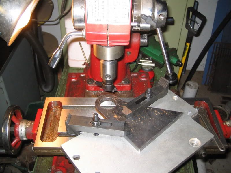
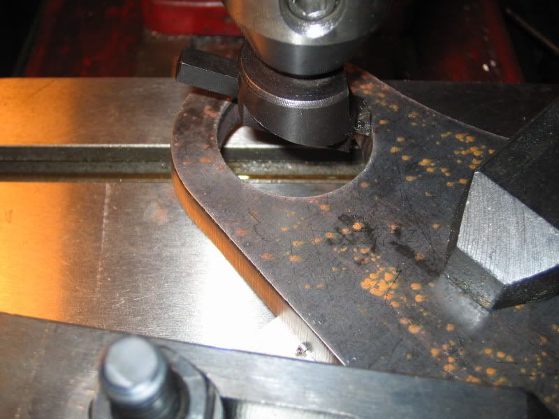
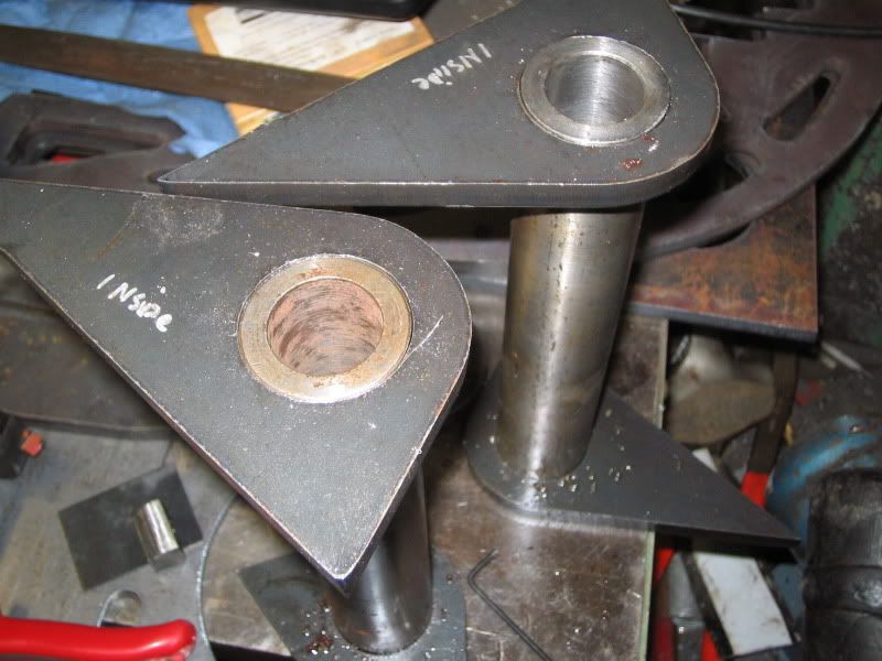
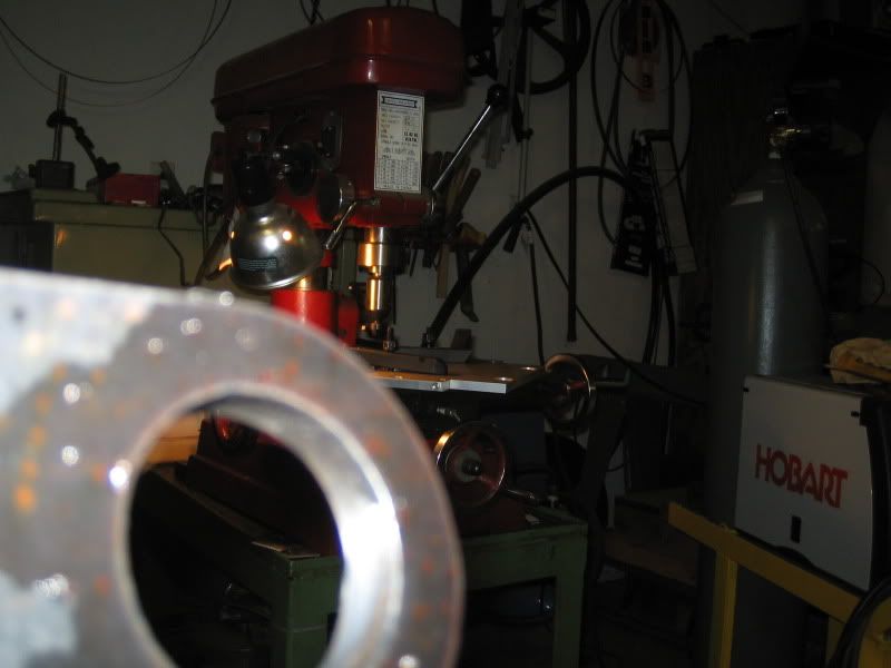
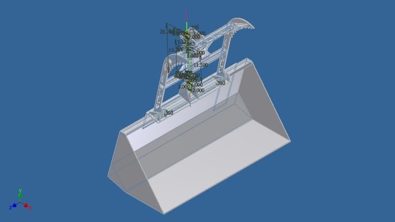
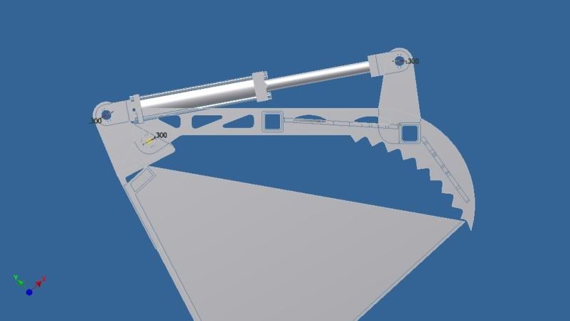
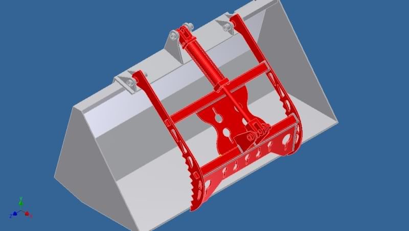
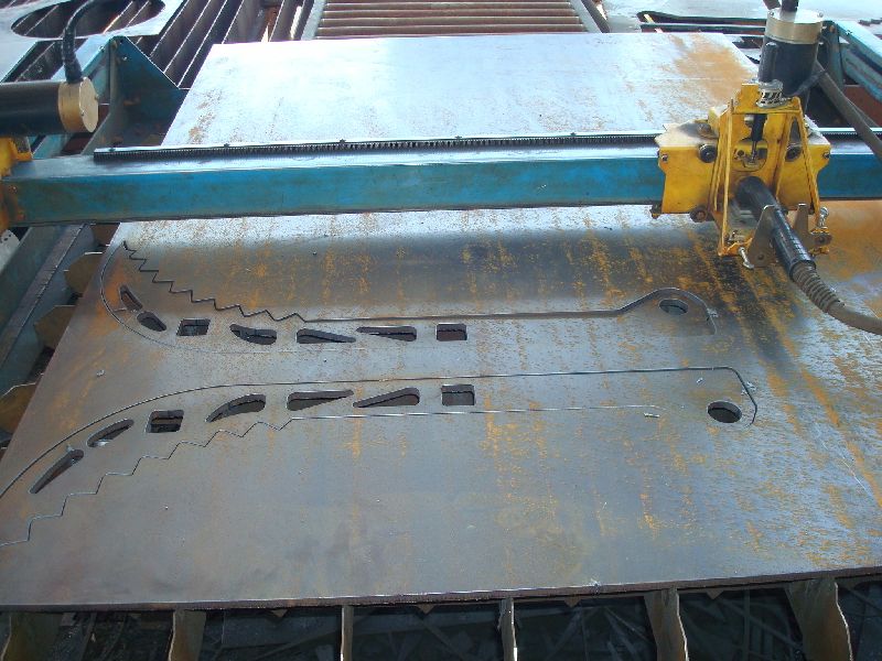
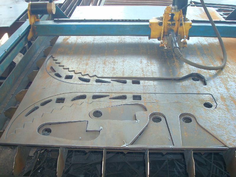
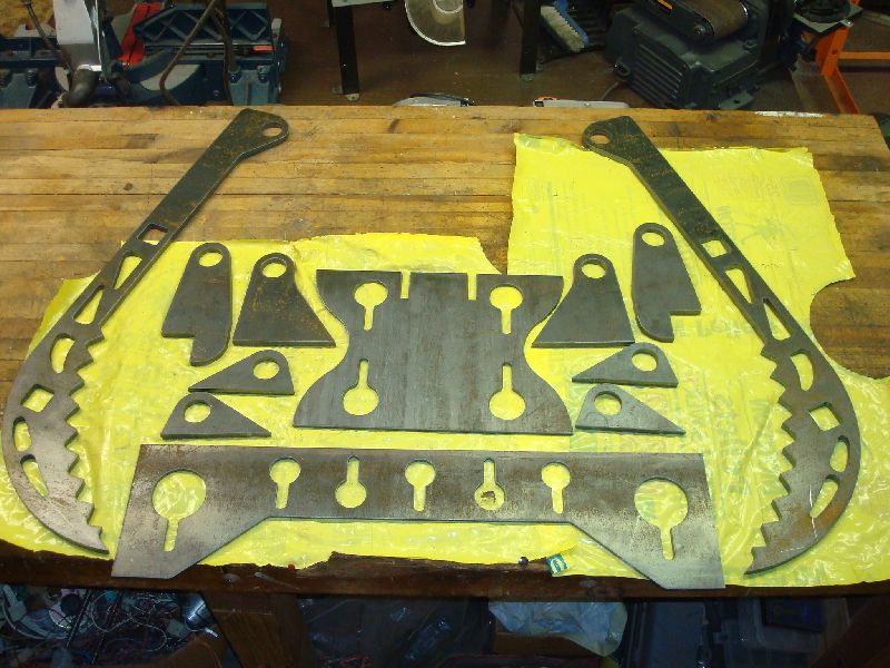
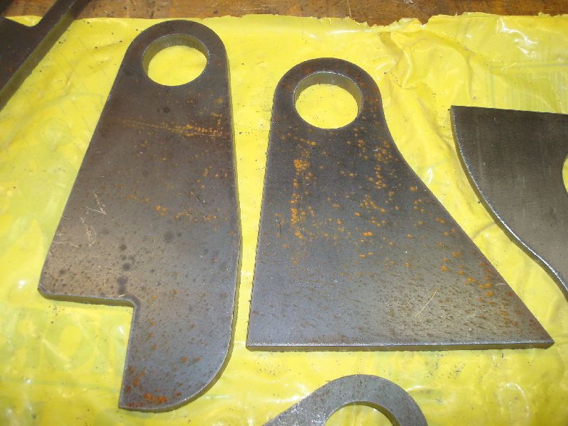
I designed and built a bucket grapple with some VERY generous help from Larry (Gugliols) in plasma cutting the parts. The design is based on an original one by Rob (3RRL) but scaled up for my Koyler 195 loader. It started with Larry sending the 2-D AutoCad drawings scaled up for me. Then we got into cylinder options and of course I wanted to use the cheapest ASAE cylnder and that screwed everything up - you know it gets complicated trying to optimize with pencil and paper.

I then made up this spreadsheet (employing the law of cosines) so I could quickly try different geometries and even use "goal seek" in the Excel tools to get what I wanted. Here is a version that allows pretty easy entry of dimensions for any type of hydraulic arm. I threw in a graphic to identify the dimensions called out in the spreadsheet. It will predict the tip force and speed through the range of motion and graph them instantly.

To open the spreadsheet you will have to change the file extension from .txt to .xls.
 
Last edited:
   / Grapple CAD build with geometry calculations.
  • Thread Starter
#2  
After figuring out the basic swing geometry in 2-D I built a 3-D model in Inventor.


It lets me check things like the predicted jaw position when fully closed and the clearance between the cylinder and the connection tube (which Larry noticed isn't much).

 
   / Grapple CAD build with geometry calculations.
  • Thread Starter
#3  
I was still getting the hang of Inventor 2010 - I got the upgrade in the middle of the project. How do my welds look?


Since the parts were to be plasma cut we didn't want to do anything as boring as round holes to reduce the weight of the jaws. I drew up some pseudo-truss, curvy cutouts plus plenty of chain keyholes. In final form I got rid of the cutouts at the base end of the jaw profiles because I was concerned about resistance to any side loading. Everything forward of the first cross tube is tied together in the weldment.


Of course the whole thing is based on Larry's overall design and he had plenty of input throughout. What a great guy. It sure pays to belong to these forums.

Hmmm, I wonder what it will look like in action?
The motion in the video is totally driven by the length of the cylinder. You can see the extra speed approaching fully up.


Here's a smoother video using a 10 second cycle.
 
   / Grapple CAD build with geometry calculations.
  • Thread Starter
#4  
Next Larry took my part sketches and loaded the geometry into the CNC plasma cutter. Here is his message showing the plasma work:

[quote author=gugliols ]
OK check this out:


The pseudo truss look is :cool: 
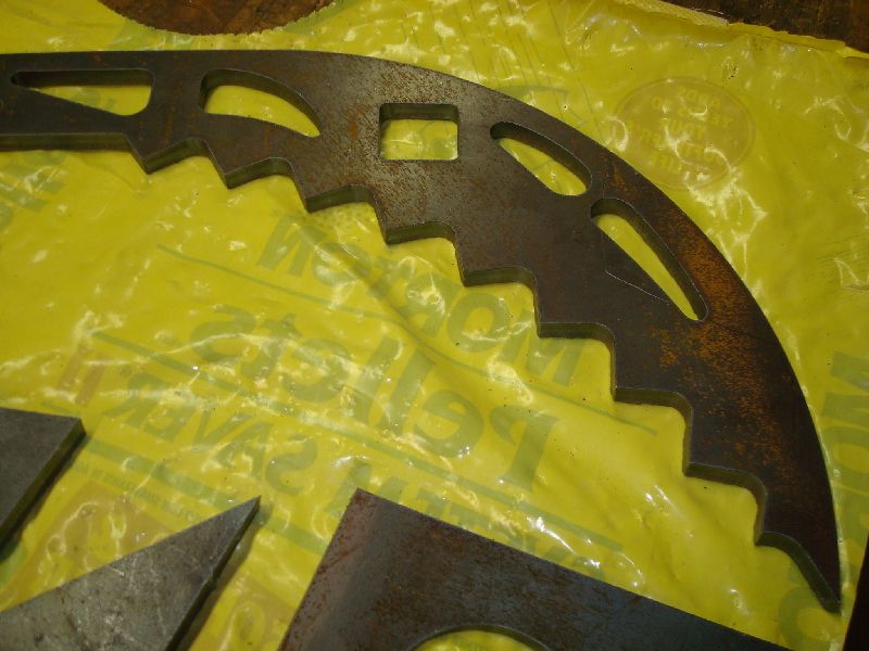
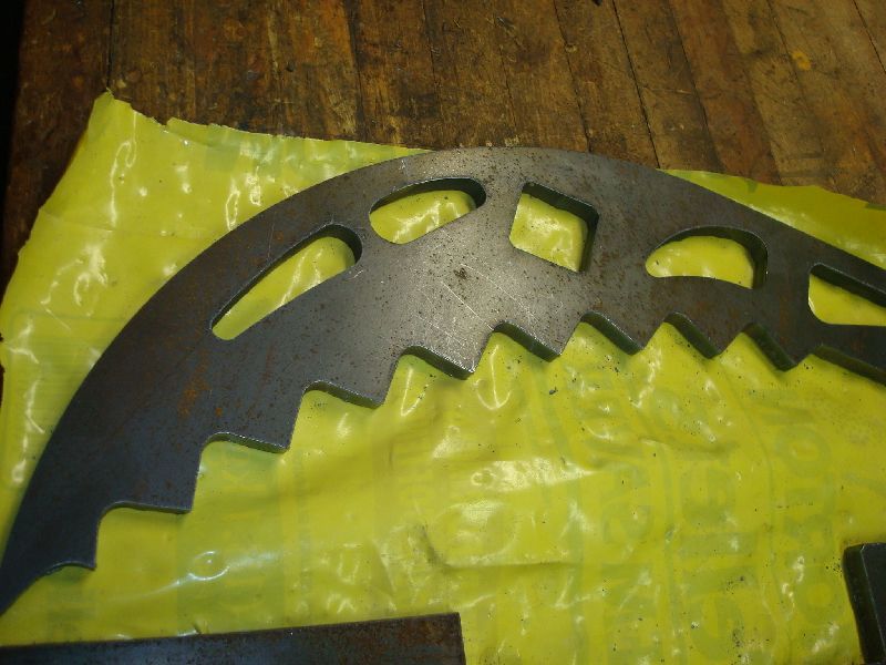
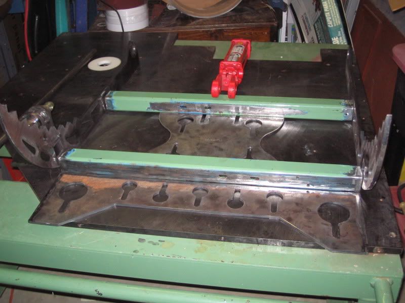
, I prefer to call it "Roswell Alien Hieroglyphics" because it's looks just like plasma cutting on the alien ship that crash landed in New Mexico way back in 1947 ;) Do you think they came out OK?


Larry[/quote]
 
   / Grapple CAD build with geometry calculations.
  • Thread Starter
#5  
After I got the parts the bushing holes needed to get bored out a little due to the taper of the plasma cuts. I managed to bore the 1.5" bushing holes with the fly cutter. The Cobalt steel tool I first used was dulling after 1 cut so
I went to a lathe tool with a carbide insert. I think the scale on the inside of the hole was dulling the steel.

I used trial and error to set the tool to 1.5", then indexed to the slightly oversized entrance of the plasma cut holes by aligning the tool at the 4 quadrants of the hole. With the lathe tool extending out the back of the cutter the depth of cut was limited so I could just cut 1 hole at a time.


The plasma start notch chipped my insert so I had to rotate it.

Big piece on the little mill:
[/
 
   / Grapple CAD build with geometry calculations. #6  
How do my welds look?


For once I must say those welds do look a "little" better than mine, I suppose ;) :cool:

MAN Brad that thing is totally awesome! Best virtual grapple I ever saw. Thanks for your generous compliments too.

It's taking shape! Won't be long now will it :D.


Larry
 
   / Grapple CAD build with geometry calculations. #7  
Brad, nice design! I really need to install Inventor on my computer.
 
   / Grapple CAD build with geometry calculations. #8  
Guys- Two things- Brad-Talk to me about "Inventer"! I'm a Google Sketch-Up buff! Free? Cost, if not. Easy to learn,etc,etc,etc. And, Larry after reading your entire Dump Trailer thread, I see your a Harbor Freight fan. Whats with that multi tool Machine (Shop?) unit? Feel it's worth the cost? ~Scotty

This one:http://www.harborfreight.com/cpi/ctaf/displayitem.taf?Itemnumber=44142
 
   / Grapple CAD build with geometry calculations.
  • Thread Starter
#9  
Thanks guys,
Inventor is made by AutoDesk and they are all about revenue. I have a shared license through my work. I think a seat is about $6000. When I made the shift from 2D AutoCad to Inventor I took a week-long course which I think was worthwhile. Inventor 2010 has a totally new user interface and the 1-day class that covered that was also worthwhile. The new version also seems to do better in translating and exporting different file types. The sheet metal mode now has a working "lofted flange" feature that will let you easily build transitions and generate the flat patterns. (why it didn't before was a mystery to me)

Edit:
There is a student license available for $160. I am pretty sure it has a feature that puts a "non commercial only" disclaimer on any file created.

Back to the grapple - on a trip to Raleigh for a PENC meeting I made a stop at Agri-Supply and picked up one of these
2 X 8 ASAE RED HYDRAULIC CYLINDER - Agri Supply
and two of these
144 LONG HYD HOSE - Agri Supply

It's funny how quickly the hoses and fittings surpass the cost of the cylinder.

Larry and Rob have strongly recommended using a solenoid valve with a switch on the joystick to control the grapple and that is definitely in my future but for now I'll be running it off a rear remote.
 
Last edited:
   / Grapple CAD build with geometry calculations.
  • Thread Starter
#10  
I got all of the bushings cut and at least solidly tacked into place. I trued an end of each bushing on the lathe and used step blocks to get the spacing I wanted, then clamped everything to the table for alignment. I don't feel like my little mig is as hot as I want for this so I'll be finishing the welds with my engine driven welder.


Tractor & Equipment Auctions

2007 Ford Crown Victoria Sedan (A44572)
2007 Ford Crown...
Makinex Jack Hammer Trolley (A45336)
Makinex Jack...
2025 Wolverine 60in. Forklift Forks (A47484)
2025 Wolverine...
Dock-Master Pads (A47484)
Dock-Master Pads...
2025 AllMetal K0720 UNUSED 20 ft. Bi-Parting Metal (A47484)
2025 AllMetal...
2025 BisonTek BT360 UNUSED Riding Skid Steer (A47484)
2025 BisonTek...
 
Top